Decelerating Device for Air Conveyed Material

a technology of air conveying device and material, which is applied in the direction of broadcast seeders, planting, and sowing, etc., can solve the problems of material being conveyed being trapped in the cyclonic, material being caught in the conical air flow, and inadvertently exhausted ou

Active Publication Date: 2012-12-13
TREAD ENTERPRISES
View PDF1 Cites 13 Cited by
  • Summary
  • Abstract
  • Description
  • Claims
  • Application Information

AI Technical Summary

Benefits of technology

[0012]The adjustable mounting of a cap portion including a guard member spanning above the upper opening provides the advantages of both: i) protecting the center tube from debris (e.g. rain and the like) which could cause plugging, and ii) permitting the cross sectional flow area of the upper exhaust opening to be adjusted. The upper vent opening size can thus be matched to the air flow rate into the material decelerator for optimizing the performance according to different operating conditions and different equipment being used. The upper vent opening size can thus be adjusted to ensure sufficient exhausting of air to decelerate the downward flow of the seed while also preventing too much exhausting through the upper vent opening which might cause seed to escape upwardly therethrough.
[0031]By arranging the helical recessed channel to be very deep relative to the overall diameter of the center tube, a significant portion of the air flow is directed within the recessed channel to maintain the flow of material substantially within the helical path of the recessed channel instead of being exhausted upwardly with the air. The depth of the recessed channel further prevents uncontrolled spinning of lighter materials within the body of the center tube so that the material can be delivered through the material outlet at a more controllable rate.
[0049]By arranging the upper end of the inlet tube at a steep angle near the axial direction of the center tube, the material decelerating device has a compact body which is well suited for mounting in series with an air distribution tube adjacent a furrow opener in a suitable agricultural implement. The compact design of the center tube and the steep angle of the adjacent inlet tube is also well suited to being fully supported by only connection to the distribution tube of the air distribution system thereabove and the material outlet carried on the body of the furrow opener therebelow such that the device is moveable together with the opener relative to the tool bar of the implement carrying various openers thereon.

Problems solved by technology

Using the designs of the prior art however, lighter materials can be caught in the conical air flow and inadvertently exhausted out of the upper air vent instead of the product delivery opening at the bottom end.
In other instances, the material being conveyed may be trapped within the cyclonic flow of air within the separator.

Method used


Image

  • Decelerating Device for Air Conveyed Material
  • Decelerating Device for Air Conveyed Material
  • Decelerating Device for Air Conveyed Material

Examples


Embodiment Construction

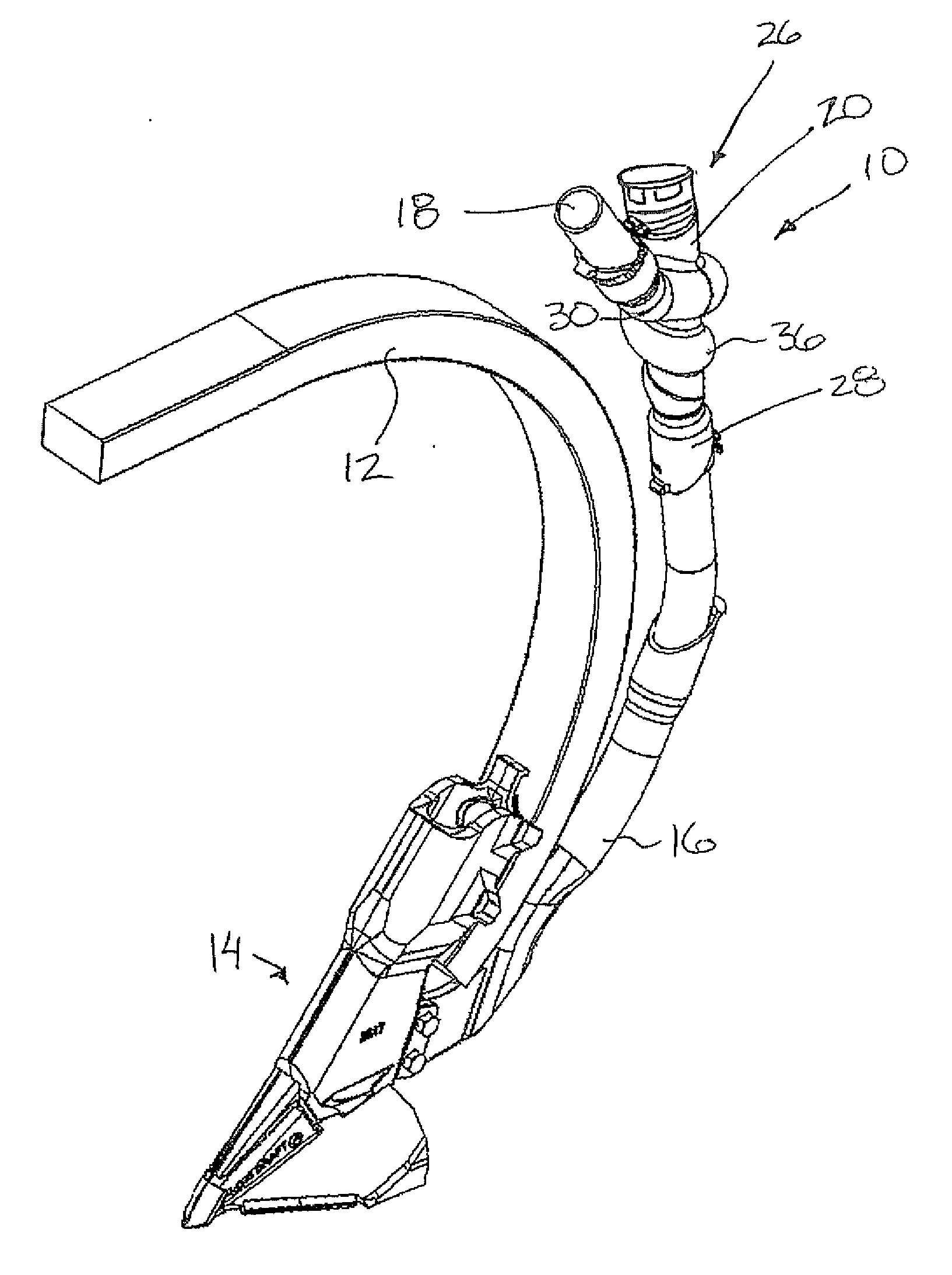
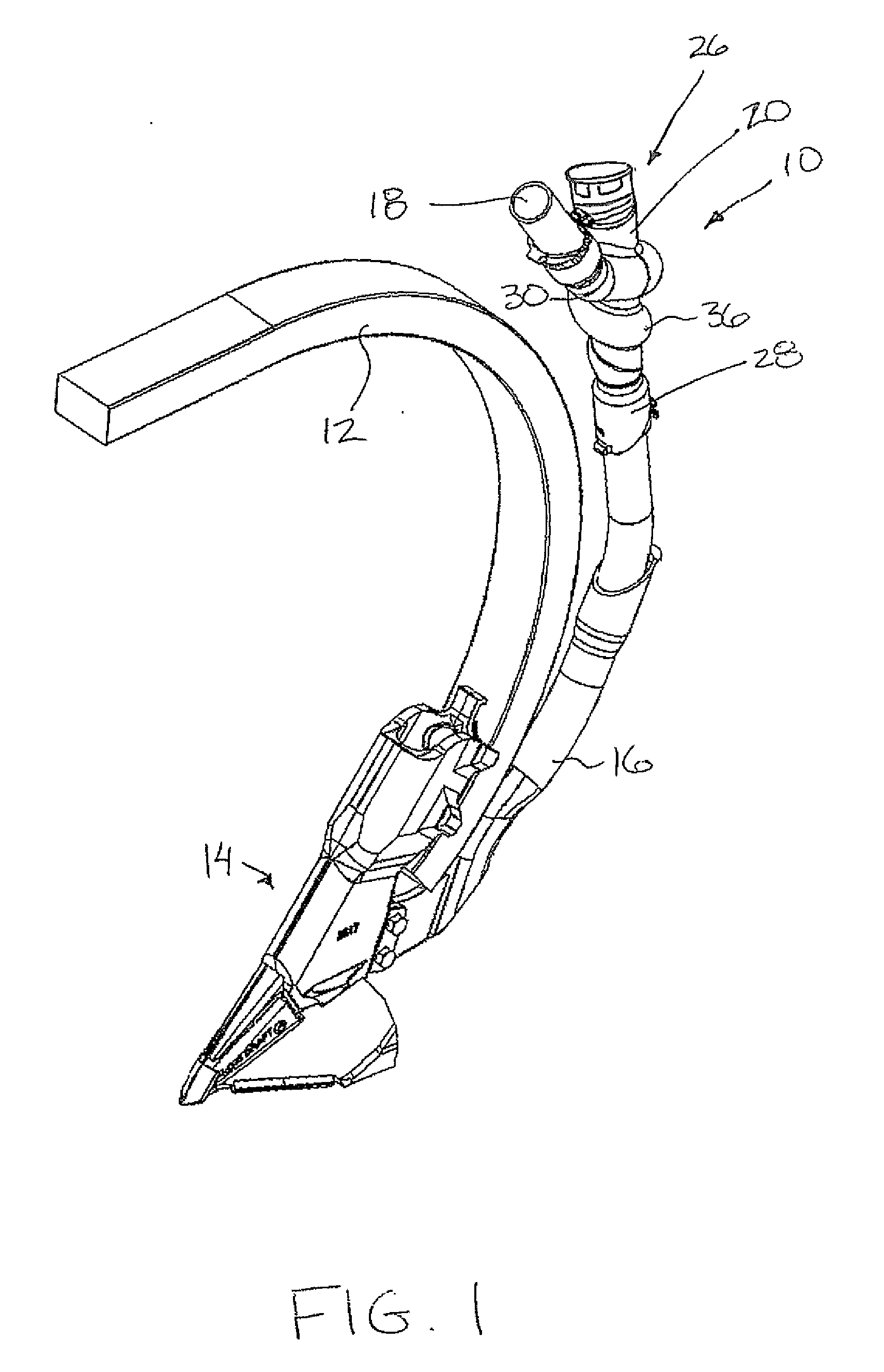
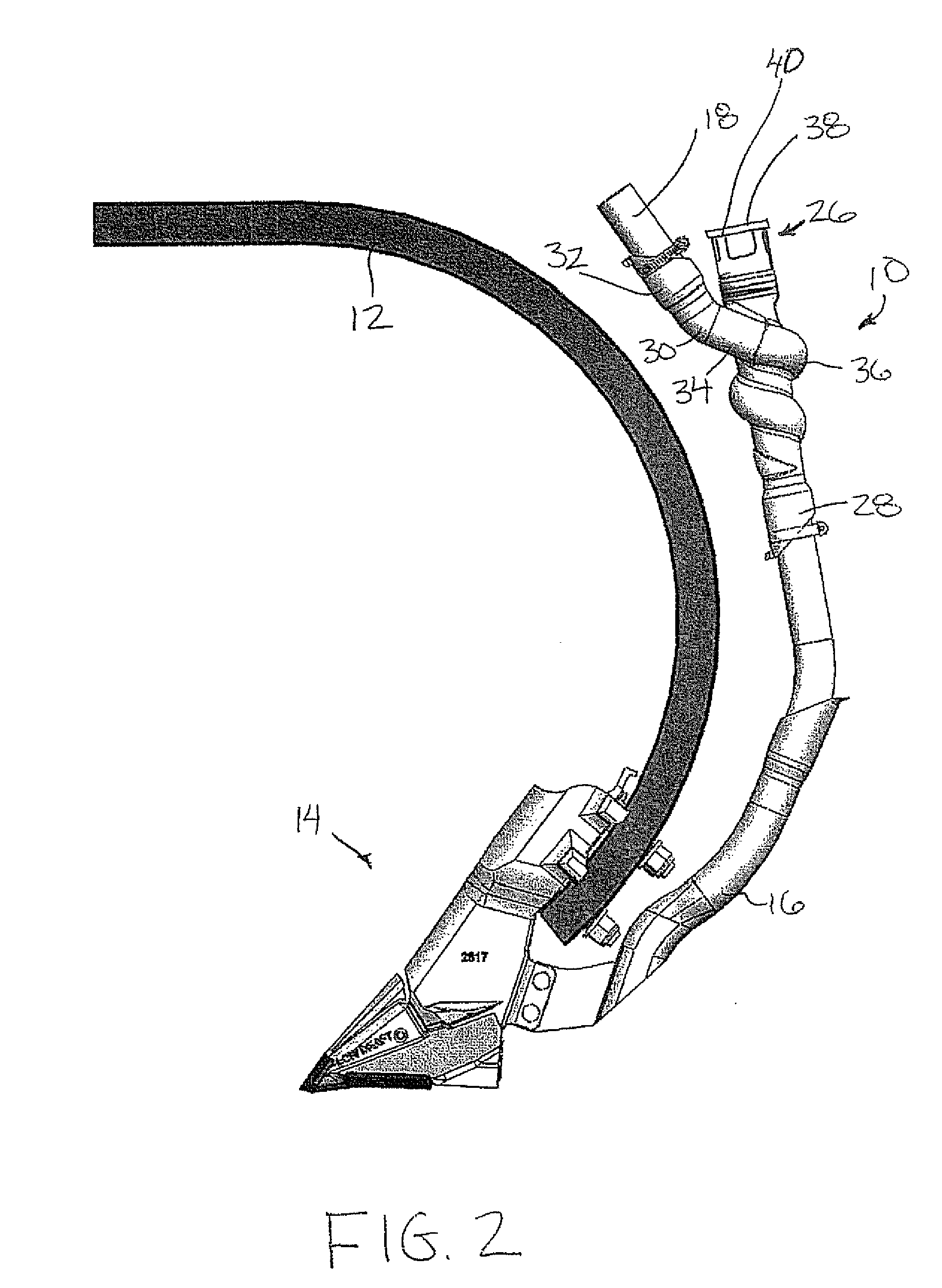
[0072]Referring to the accompanying figures, there is illustrated a material decelerating device generally indicated by reference numeral 10. The device 10 is particularly suited for use with the air distribution system of an appropriate agricultural implement for placing particulate material within respective furrows formed in the ground.

[0073]Although two embodiments are shown in the accompanying figures, the common features of the two embodiments will first be described herein.

[0074]A suitable implement typically comprises a tool bar arranged to be towed across the ground by a tractor or the like. The tool bar supports a plurality of implement shanks 12 thereon in which each shank supports a respective furrow opener 14 such that the furrow opener is resiliently suspended from the tool bar. The furrow opener 14 includes at least one material outlet 16 suitable for depositing particulate material therethrough into the furrow formed by the opener 14, for example seed or fertilizer o...


PUM


Abstract

A material decelerating device is connected in series with a distribution tube in proximity to a material outlet in an agricultural air distribution system for decelerating conveying air which placing material into a furrow in the ground. The material decelerating includes an inlet tube connected to the distribution tube to receive material and conveying air therefrom. The inlet tube is connected at an intermediate location on a center tube of the device which exhausts the air upwardly to an exhaust opening and deposits the material downwardly through an outlet opening. A cap adjustably spans the exhaust opening to vary the amount of air exhausted. The inlet tube is inclined downwardly in alignment with a helical recessed channel within the center tube to guide material to the outlet.

Description

[0001]This application claims the benefit under 35 U.S.C. 119(e) of U.S. provisional application Ser. No. 61 / 548,244, filed Oct. 18, 2011 and U.S. provisional application Ser. No. 61 / 494,964, filed Jun. 9, 2011.FIELD OF THE INVENTION[0002]The present invention relates to a material decelerating device for use in an agricultural air distribution system which pneumatically conveys particulate material (for example seed and fertilizer) through distribution tubes, and more particularly the present invention relates to a material decelerating device, which can be connected between a distribution tube of the air distribution system and a material outlet on a furrow opener for exhausting the conveying air through a separate opening in the device from the particulate material deposited into the material outlet, for example as in a conical separator type device.BACKGROUND[0003]In agriculture, it is common to make use of air distributions systems for delivery of seed or fertilizer to furrows ...

Claims


Application Information

Patent Timeline
Patent Type & Authority Applications(United States)
IPC IPC(8): A01C7/08
CPCA01C7/082A01C7/042A01C7/084A01C7/201A01C7/20A01C7/206A01C7/16
Inventor CRUSON, BRIAN
Owner TREAD ENTERPRISES
Why Eureka
Try Eureka