

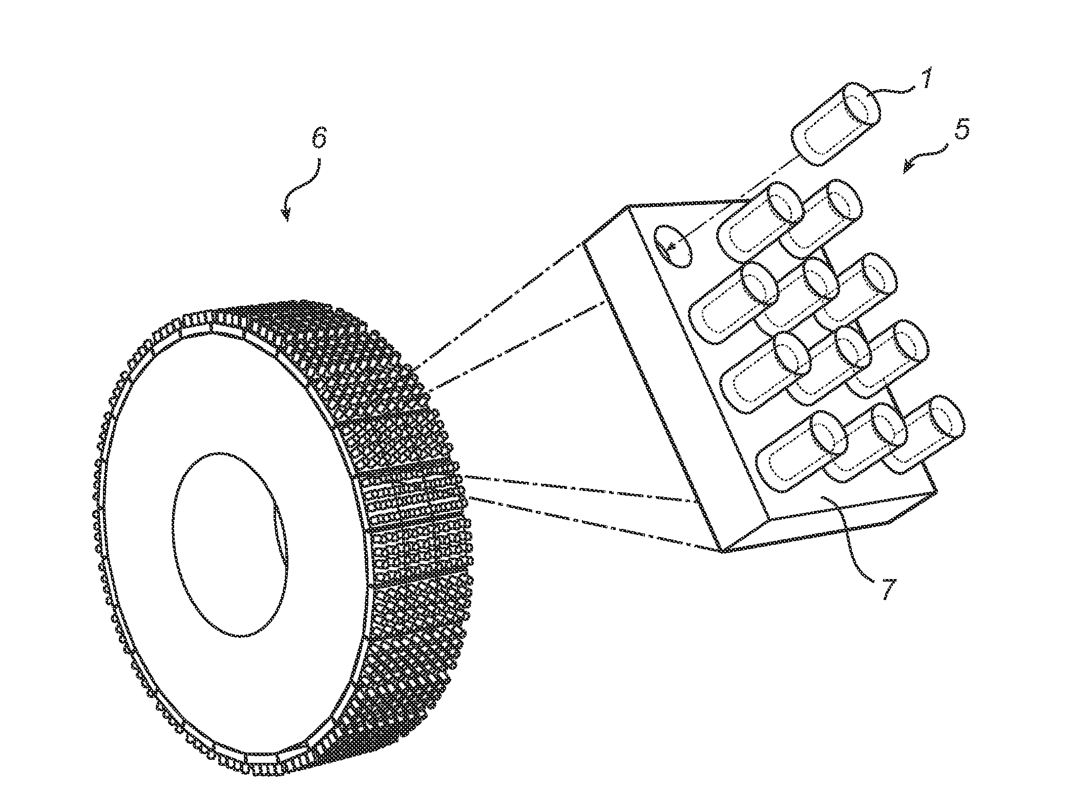
Bimaterial elongated insert member for a grinding roll
a technology of insert members and bimaterials, which is applied in the field of elongated insert members for grinding rolls, can solve the problems of failure of insert members, failure of use, and reduced insert member failure, and achieve the effects of simple shape, easy manufacturing, and convenient us
- Summary
- Abstract
- Description
- Claims
- Application Information
AI Technical Summary
Benefits of technology
Problems solved by technology
Method used
Image

Examples
first embodiment
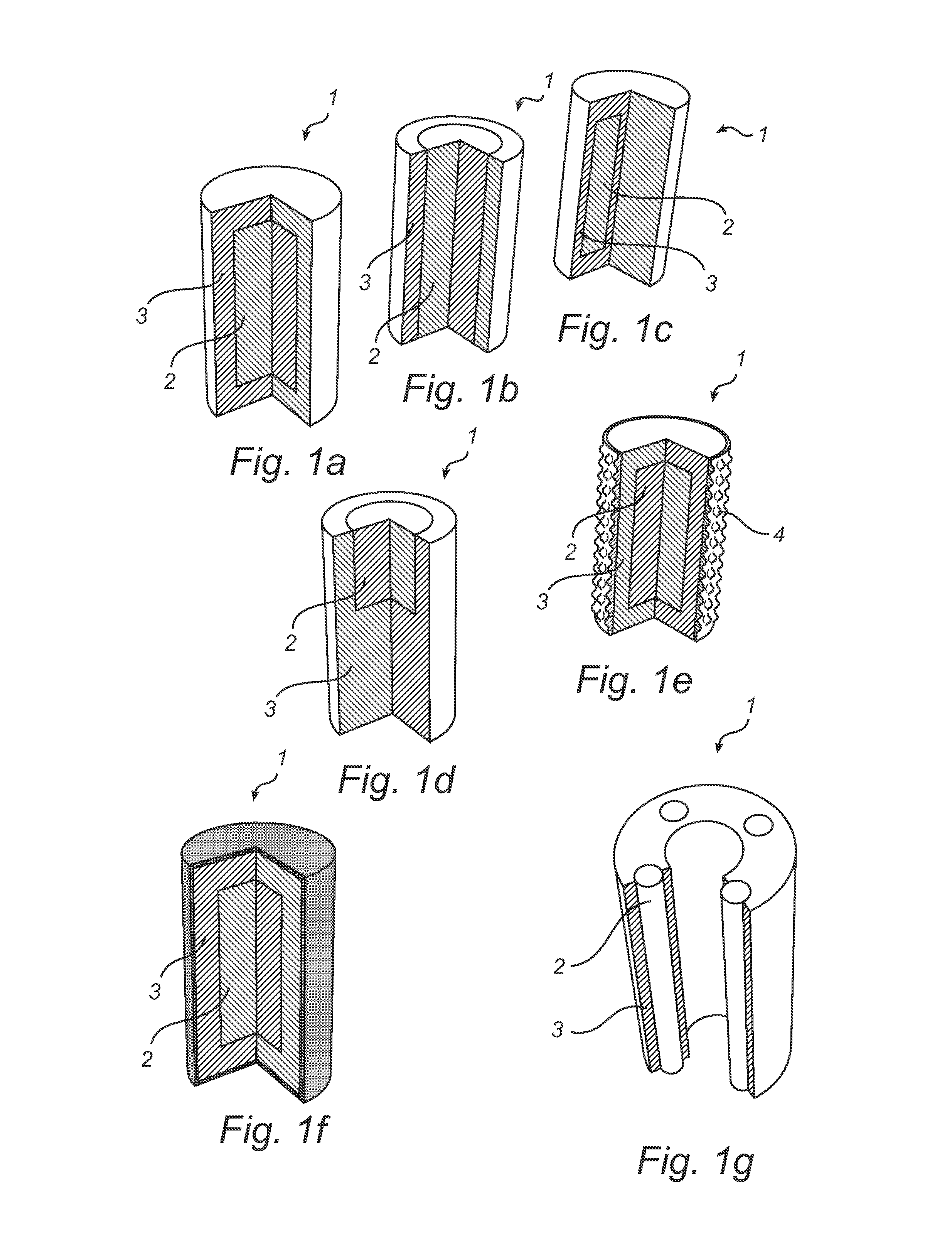
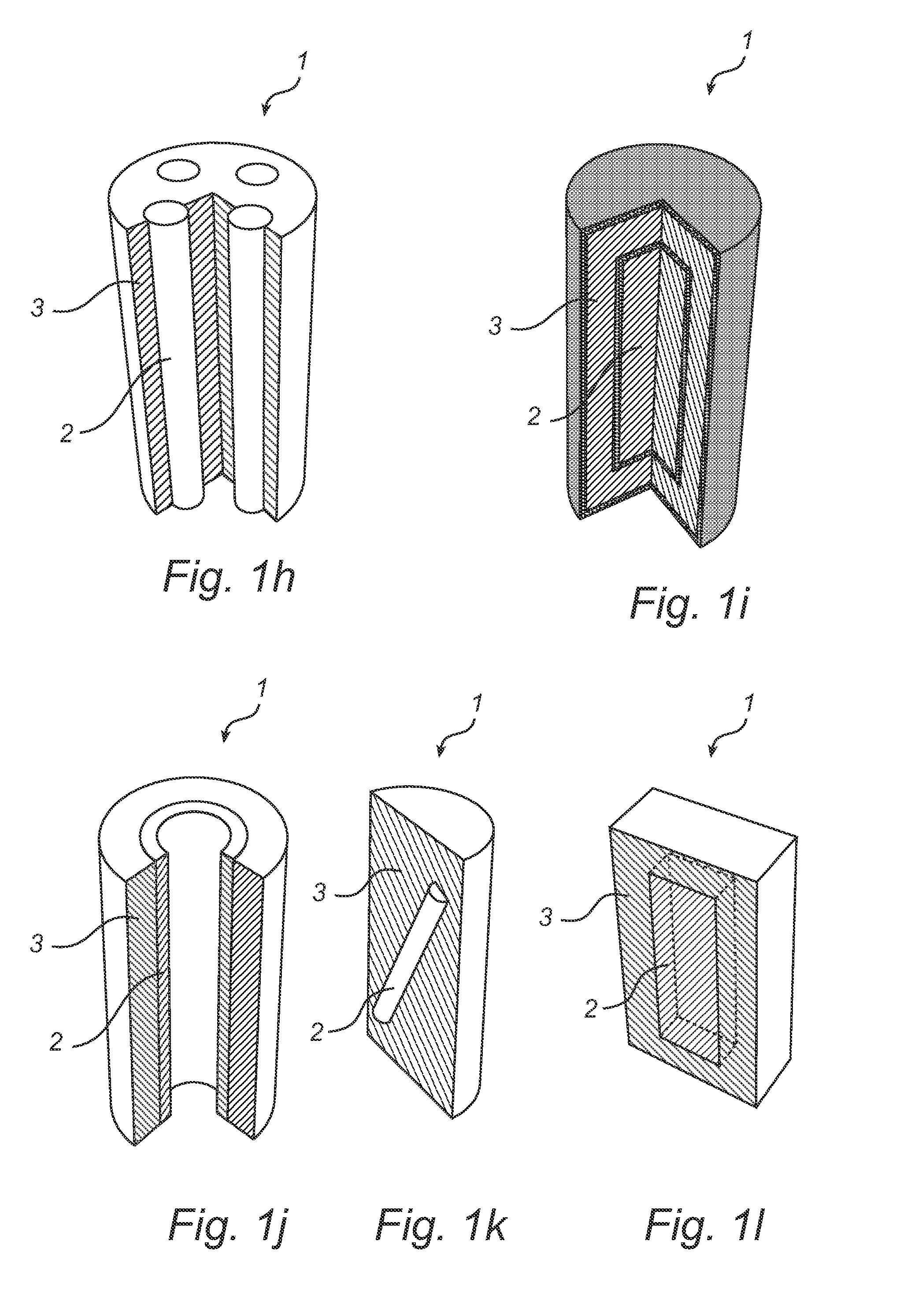
[0034]FIG. 1a illustrates an insert member 1 for a grinding roll for heavy wear operation according to the invention. The cross-section of the insert member 1 is cylindrical and it has the shape of a pin. The insert member 1 has a core 2 of a first material having a first hardness. The core 2 is cylindrical and extends in the longitudinal direction of the insert member 1. The geometric axis of the core 2 is aligned with the geometric axis of the inert member 1. The insert member 1 further has a body 3 of a second material having a second hardness, which body 3 completely encloses the core 2. The first hardness is greater than the second hardness. The first material, that is to say the material of the core 2 of the insert member 1, is preferably constituted by a metallic material, ceramic material or a combination thereof. However, other material solutions for the core 2 of the insert member 1 are naturally also possible. The first material has a preferred hardness from at least 600 ...
second embodiment
[0035]In FIG. 1b, the insert member 1 according to the invention is illustrated. The core 2 is cylindrical and extends along the entire length of the insert member 1 in the longitudinal direction. The geometric axis of the core 2 is aligned with the geometric axis of the inert member 1. The body 3 of the insert member 1 radially encloses the core 2. The core 2 is thus exposed on the top and the bottom of the insert member 1, when standing in a vertical direction.
[0036]FIG. 1c illustrates the insert member 1 according to a third embodiment of the invention. The core 2 is cylindrical and extends in the longitudinal direction of the insert member 1. The geometric axis of the core 2 is offset or displaced with respect to the geometric axis of the insert member 1. The body 3 of the insert member 1 completely encloses the core 2. In FIG. 1d, the insert member 1 according to a fourth embodiment of the invention is illustrated. The core 2 is cylindrical and extends from the top of the inser...
fifth embodiment
[0037]FIG. 1e illustrates the insert member 1 according to the invention. The core 2 is cylindrical and extends in the longitudinal direction of the insert member 1. The geometric axis of the core 2 is aligned with the geometric axis of the insert member 1. The body 3 of the insert member 1 completely encloses the core 2. The outer surface 4 of the insert member 1 is profiled. That is to say, the outer surface 4 of the insert member 1 is provided with bulges in order to help keeping the material to be crushed or pulverized in the spaces created between the insert members 1 when provided on a roll, such that a protective autogenous layer is created and maintained during use of that roll. The bulges may be formed integrally with the body 3 or may be provided as a sleeve arranged on said body.
PUM
 Abstract
Description
Claims
Application Information