Supercharge Your Innovation With Domain-Expert AI Agents!

Auxiliary pressure relief reservoir for crash barrier

a technology of crash barrier and reservoir, which is applied in the direction of roadway safety arrangements, traffic restrictions, roads, etc., can solve the problems of system failure, system failure, and inability to operate during periods of inoperability of the barrier system

Active Publication Date: 2012-12-13
SAUDI ARABIAN OIL CO
View PDF20 Cites 1 Cited by
  • Summary
  • Abstract
  • Description
  • Claims
  • Application Information

AI Technical Summary

Benefits of technology

The solution effectively mitigates overpressure issues, minimizing damage to hydraulic system components, reducing downtime, and ensuring the barrier's functionality during emergency operations, thus enhancing security and reducing environmental impact.

Problems solved by technology

In order to raise the barrier rapidly, the mechanisms required are typically over-engineered.
However, problems associated with the hydraulic circuit can result in periods of inoperability of the barrier system.
Systems that raise and lower the crash barriers are prone to failure, for instance in the form of hydraulic fluid overpressure that exceed the capacity of various valves, seals or other elements in the fluid pathway.
Under normal operating conditions, hydraulic fluid is pumped from a reservoir into one of the variable volume fluid compartments (a high pressure compartment), thereby displacing the piston and causing the crash barrier to ascend or descend.
However, certain undesirable conditions may cause hydraulic fluid from a high pressure compartment of the hydraulic actuator to leak into the low pressure compartment and into the hydraulic circuit, which will be referred to as an internal leak.
If the solenoid valve is defective, any resulting overpressure conditions may cause failure in the directional control valve, system hoses, or one or more pressure gauges connected to at various positions in the hydraulic circuit.
This pressure switch is prone to failure, which diminishes control functionality of the programmable logic controller, potentially leading to overpressure conditions that may cause damage to elements in the hydraulic fluid circuit.
If the maximum pressure capacity of any of the system components is exceeded, one or more external leaks can occur, thus wasting hydraulic fluid, potentially creating environmental problems, and, of course, rendering the crash barrier inoperable during the time it takes to make the necessary repairs.
If the failure occurs in the raised position, that creates an inconvenience for the normal traffic flow in and out of the facility.
If the failure occurs in the lowered position, the facility is left vulnerable to vehicular threats.

Method used


Image

  • Auxiliary pressure relief reservoir for crash barrier
  • Auxiliary pressure relief reservoir for crash barrier
  • Auxiliary pressure relief reservoir for crash barrier

Examples


Embodiment Construction

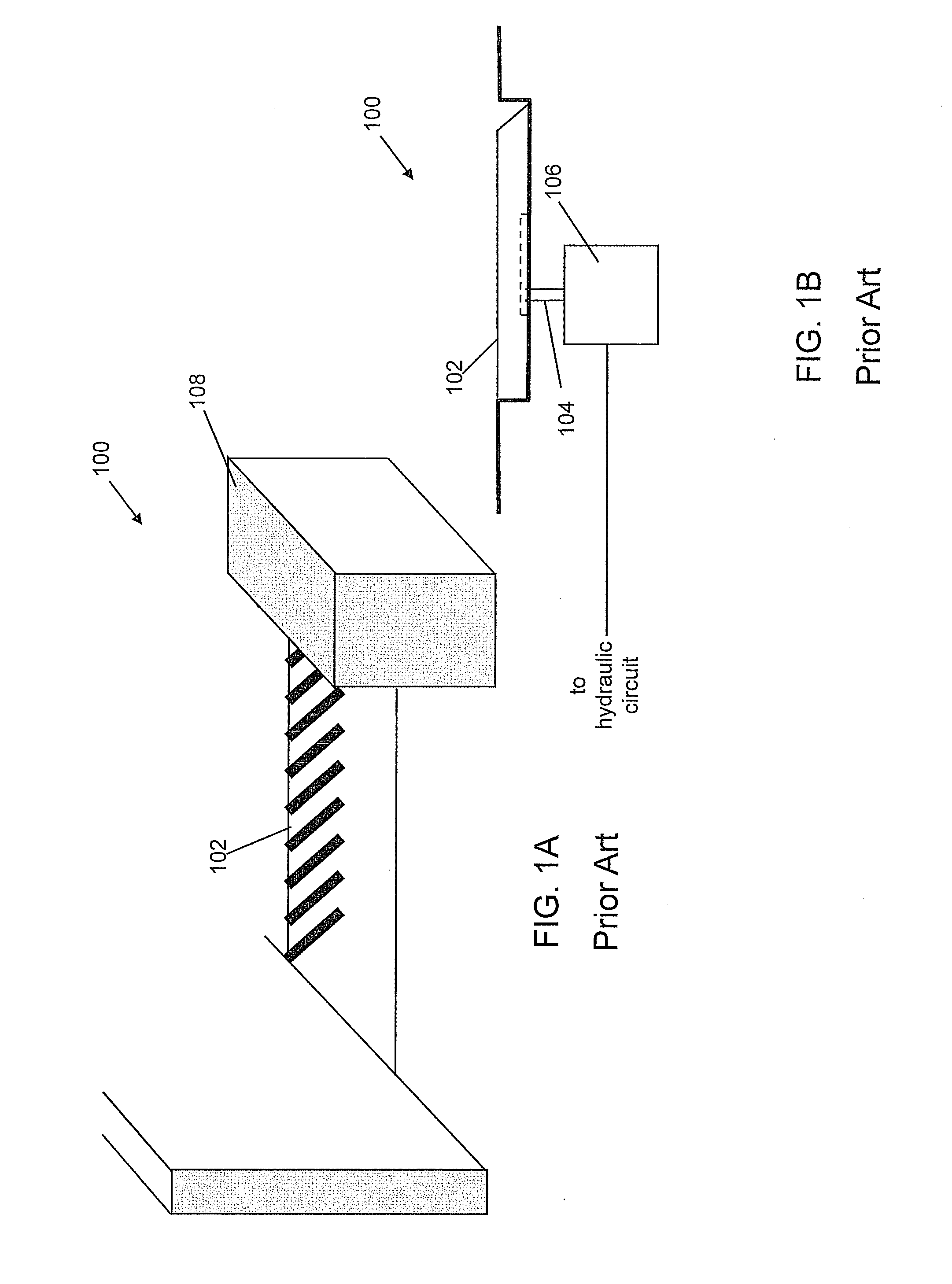
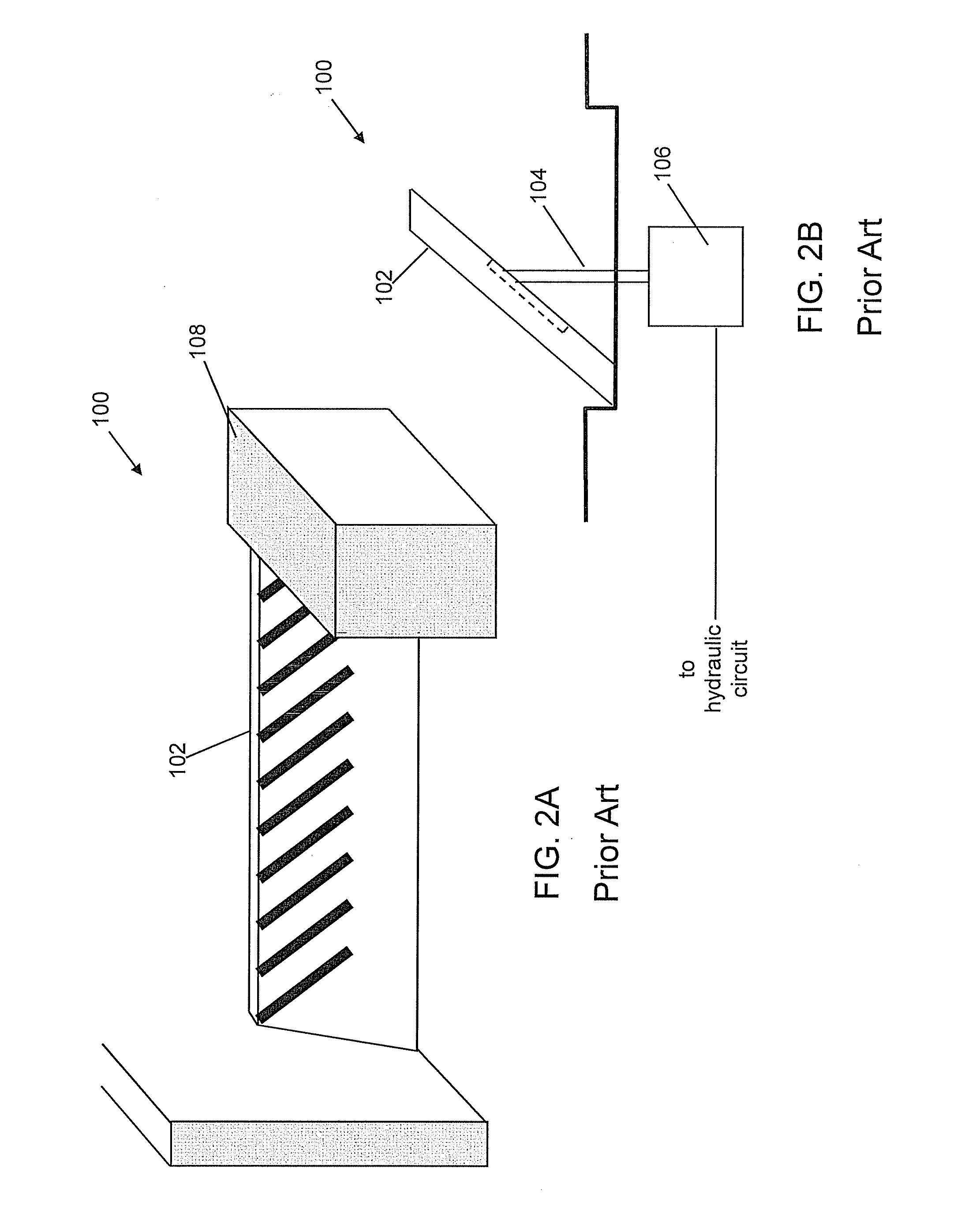
[0045]FIGS. 1A and 1B show a simplified perspective view and a sectional view of a typical prior art crash barrier system 100 having a barrier 102 in the DOWN position, and FIGS. 2A and 2B show perspective views of system 100 having the barrier 102 in the UP position. The system 100 includes the barrier 102 operably connected to a hydraulically driven piston 104 of an actuator 106. All or a portion of a hydraulic circuit for powering the lifting and retracting operations of the barrier 102 can be encased, for instance, in a housing 108.

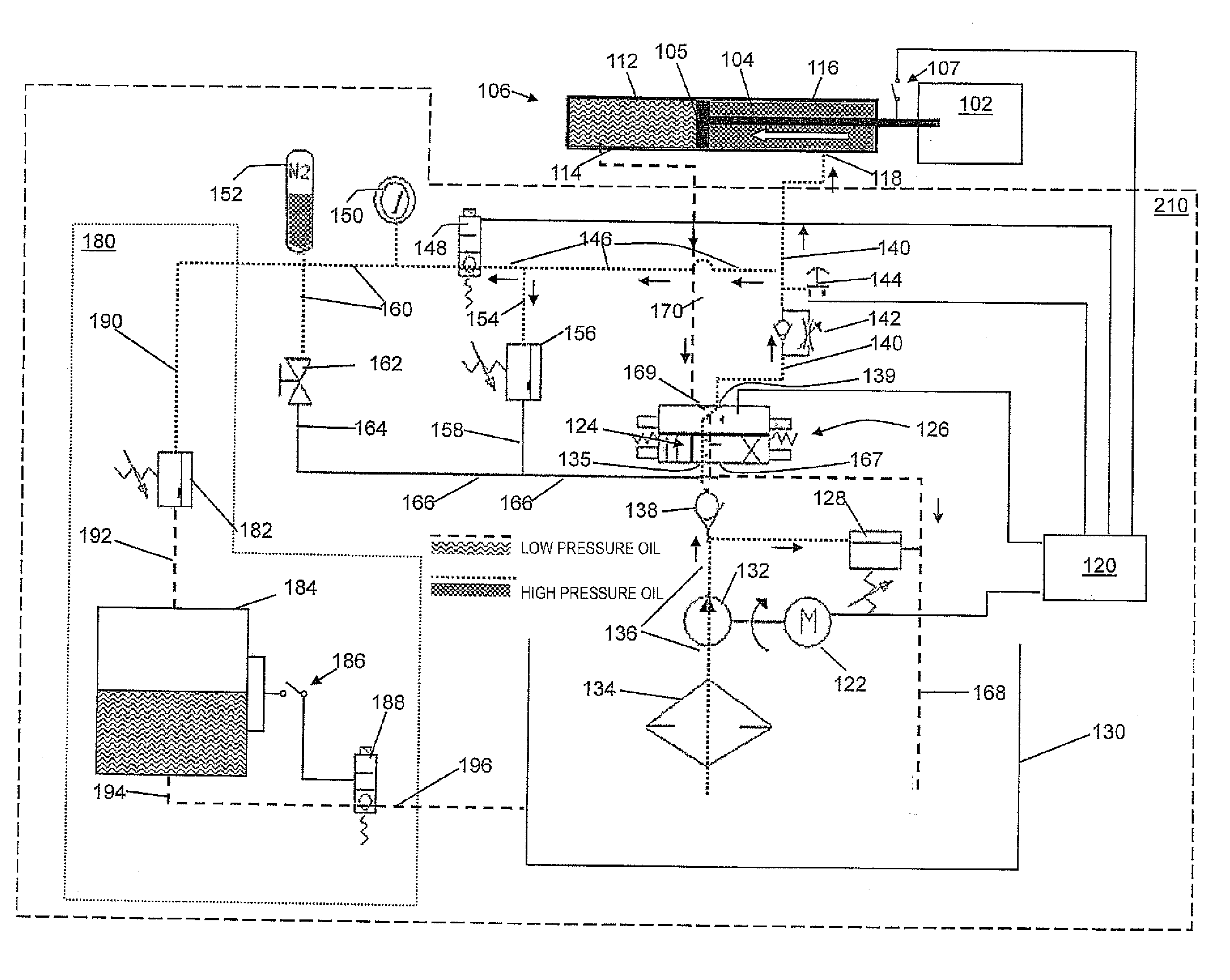
[0046]Referring to FIG. 3, a conventional hydraulic circuit 110 is schematically illustrated in fluid communication with the piston 104 of the hydraulic actuator 106. The hydraulic actuator 106 driven piston 104 includes a first end structurally connected to the crash barrier 102 and a second end that is a movable compartment wall 105 between a first variable volume fluid compartment 112 and a second variable volume fluid compartment 116. The first va...


PUM


Abstract

A crash barrier system is provided that generally includes a hydraulic actuator driven piston operably connected to a hydraulic circuit and the crash barrier. In general, the hydraulic circuit includes a normal-UP and normal-DOWN section, an emergency-UP section, and an overpressure relief sub-system. In order to automatically provide corrective action in the event of an overpressure condition, the overpressure relief sub-system includes an external pressure relief valve that is connected to the hydraulic circuit. Upon occurrence of condition that causes the hydraulic fluid pressure to exceed a predetermined value, hydraulic fluid is released through the pressure relief valve to maintain the pressure at or below the predetermined value.

Description

RELATED APPLICATIONS[0001]Not applicable.BACKGROUND OF THE INVENTION[0002]1. Field of the Invention[0003]This invention relates to hydraulic powered vehicle crash barrier systems, in particular crash vehicle barrier systems having an emergency mode of operation to rapidly raise the crash barrier.[0004]2. Description of Related Art[0005]Vehicle crash barriers are well known for use as anti-terrorism and other security measures. Generally, a crash barrier pivots between a lowered position in which vehicles easily pass over it, and a raised position that prevents passage of vehicles. In order to sustain an impact from a potential vehicular threat, the barriers have substantial mass and are constructed of very heavy gauge steel, and may include concrete.[0006]In order to raise the barrier rapidly, the mechanisms required are typically over-engineered. Examples of mechanisms to raise and lower the barrier based on hydraulics are described, for instance, in U.S. Pat. Nos. 4,850,737, 4,627...

Claims


Application Information

Patent Timeline
Patent Type & Authority Applications(United States)
IPC IPC(8): E01F13/08E01F15/00
CPCE01F13/12E01F13/08E01F13/123
Inventor AL-QAHTANI, BANDAR ALI
Owner SAUDI ARABIAN OIL CO
Features
  • R&D
  • Intellectual Property
  • Life Sciences
  • Materials
  • Tech Scout
  • Unparalleled Data Quality
  • Higher Quality Content
  • 60% Fewer Hallucinations
Learn More