Vacuum pump

US20120315165A1Active Publication Date: 2012-12-13LEYBOLD HERAEUS GMBH & CO KG
3 Cites 9 Cited by

Patent Information

Authority / Receiving Office
US · United States
Current Assignee / Owner
Publication Date
2012-12-13

Smart Images

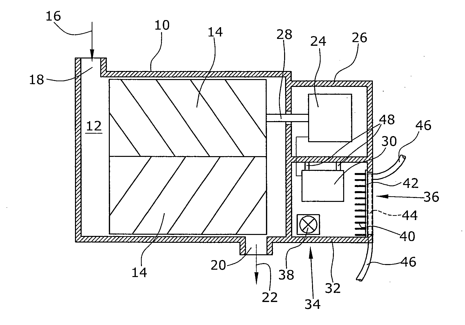
  • Figure 1
    Figure 1
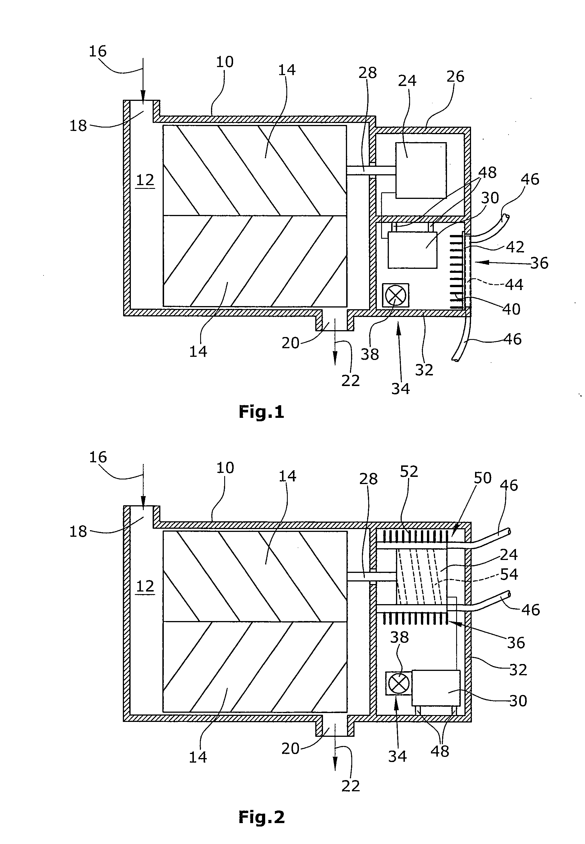
  • Figure 2
    Figure 2
Patent Text Reader

Abstract

A vacuum pump comprises pumping elements arranged in a pumping chamber. An electric motor drives the pumping element. A frequency inverter is provided for changing the rotational speed of the electric motor. The frequency inverter is arranged in a frequency inverter housing immediately connected to the pump housing. An air cooler and a liquid cooler are arranged in the frequency inverter housing to cool the frequency inverter.
Need to check novelty before this filing date? Find Prior Art

Description

BACKGROUND

[0001] 1. Field of the Disclosure

[0002] The disclosure refers to a vacuum pump, in particular a screw-type vacuum pump, a Roots vacuum pump or a rotary vane vacuum pump.

[0003] 2. Discussion of the Background Art

[0004] Vacuum pumps comprise pumping elements arranged in a pumping chamber formed by the pump housing and serving to convey a fluid, especially a gas such as air. The pumping elements are usually driven by an electric motor. For a simple variation of the rotational speed of the vacuum pump it is known to use frequency inverters, so as to be able to change the motor speed in a simple manner. A frequency inverter is a sensitive electronic component. To allow a good cooling and a vibration-free arrangement of the frequency inverters, it is known to provide them in a control cabinet independent from the vacuum pump and separately from the pump. However, this is troublesome in particular because of the necessary wiring between the control cabinet and the electric motor of t...

Examples

Embodiment Construction

[0030]The Figures each very schematically illustrate screw-type vacuum pumps as examples. Here, a housing 10 defines a pumping chamber 12 in which two pumping screws 14 are arranged as pumping elements which rotate in opposite directions. Usually, this is effected via a transmission not illustrated in the sketches and arranged between the two screw rotors 14.

[0031]The rotation of the two pumping elements causes an intake of a medium in the direction of an arrow 16 through an inlet opening 18 and an ejection of the medium though an outlet opening 20 in the direction of an arrow 22.

[0032]According to the first preferred embodiment of the disclosure, illustrated in FIG. 1, an electric motor 24 is arranged in a portion 26 of the housing.

[0033]The electric motor 24 is connected to one of the pumping screws 14 via its output shaft 28.

[0034]For a control of the rotational speed of the electric motor 24, a frequency inverter 30 is provided that is electrically coupled to the electric motor ...