Marine Threat Monitoring and Defense System

a technology of applied in the field of marine threat monitoring and defense system, can solve problems such as threat to a structure conducting set operation and threat to the “s

Active Publication Date: 2012-12-13
CONCEPT SYST
View PDF11 Cites 49 Cited by
  • Summary
  • Abstract
  • Description
  • Claims
  • Application Information

AI Technical Summary

Benefits of technology

[0011]As will be appreciated, having correct information is helpful in making decisions to defend the target vessel. To accomplish this goal, the system uses real-time data management, data communications, vessel tracking, and object tracking. To then aid analysis and decision-making, the system operators can view the latest imagery and observed position data of these elements. Moreover, the predictive features of the system uses ocean current prediction models, transponder observations, and obstacle tracking so the system can make predictions into the future and operators can model possible scenarios that will occur.
[0012]In the end, the disclosed system provides the system operators with relevant information to take a course of action to protect the target vessel from incoming threats. Making incorrect decisions could be very costly and impact various financial, safety, and environmental issues. Therefore, the monitoring system advantageously enables operators to order how the target vessel can be defended, shutdown and withdrawn from the region if risk levels become too high.

Problems solved by technology

An icy region, such as the arctic, has icebergs, ice floes, and other obstacles that float in the ocean waters and are carried by currents and other weather conditions, and such obstacles can threaten a structure conducting set operations (e.g., a vessel stationed for drilling or production or a vessel with a planned route for exploration) in such a region.
Just as ice can threaten operations, these marine obstacles can threaten the “set” structure as it conducts stationed or planned operations in the waterways.

Method used


Image

  • Marine Threat Monitoring and Defense System
  • Marine Threat Monitoring and Defense System
  • Marine Threat Monitoring and Defense System

Examples


Embodiment Construction

[0020]A. Overview of Monitoring System

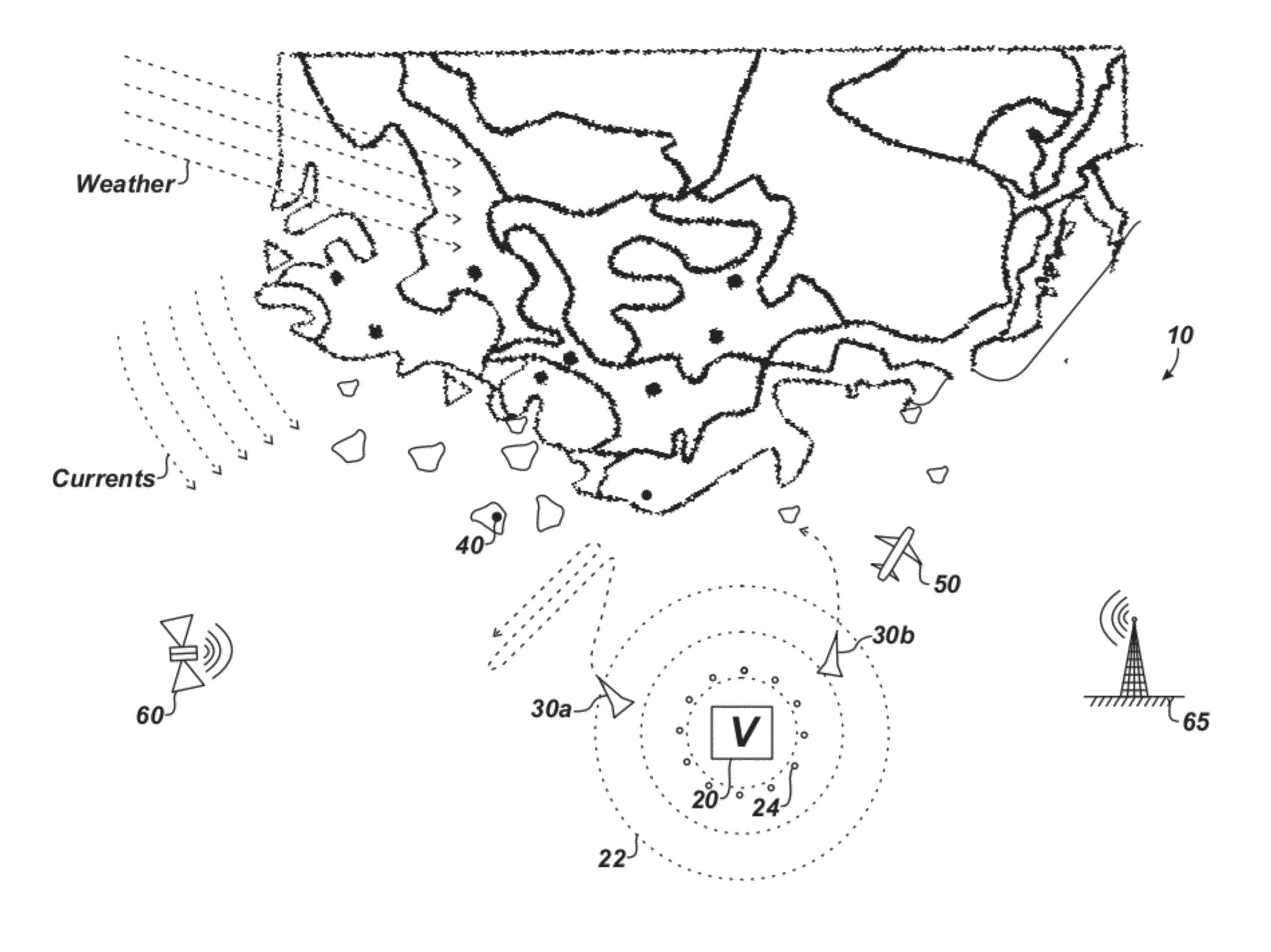
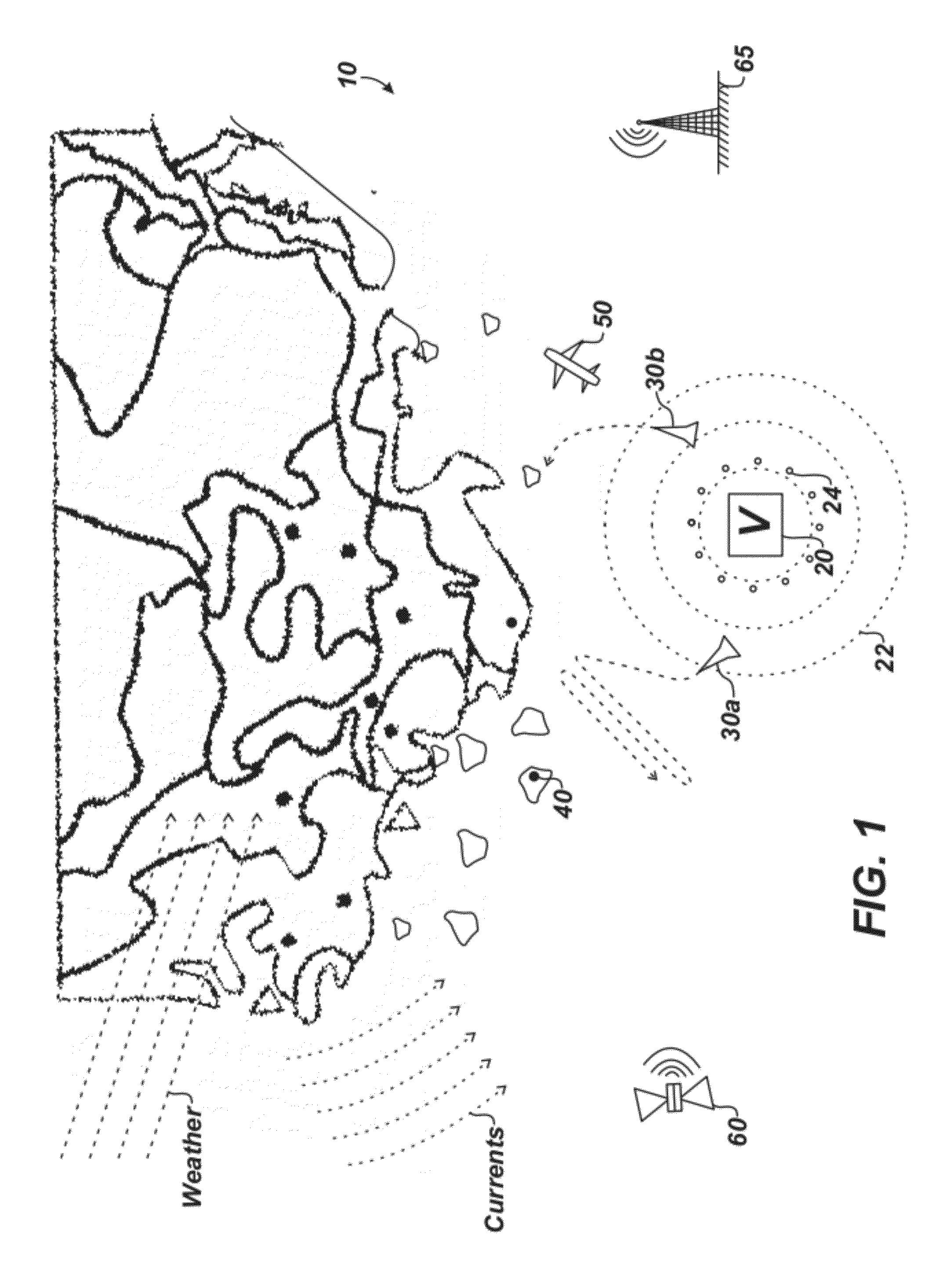
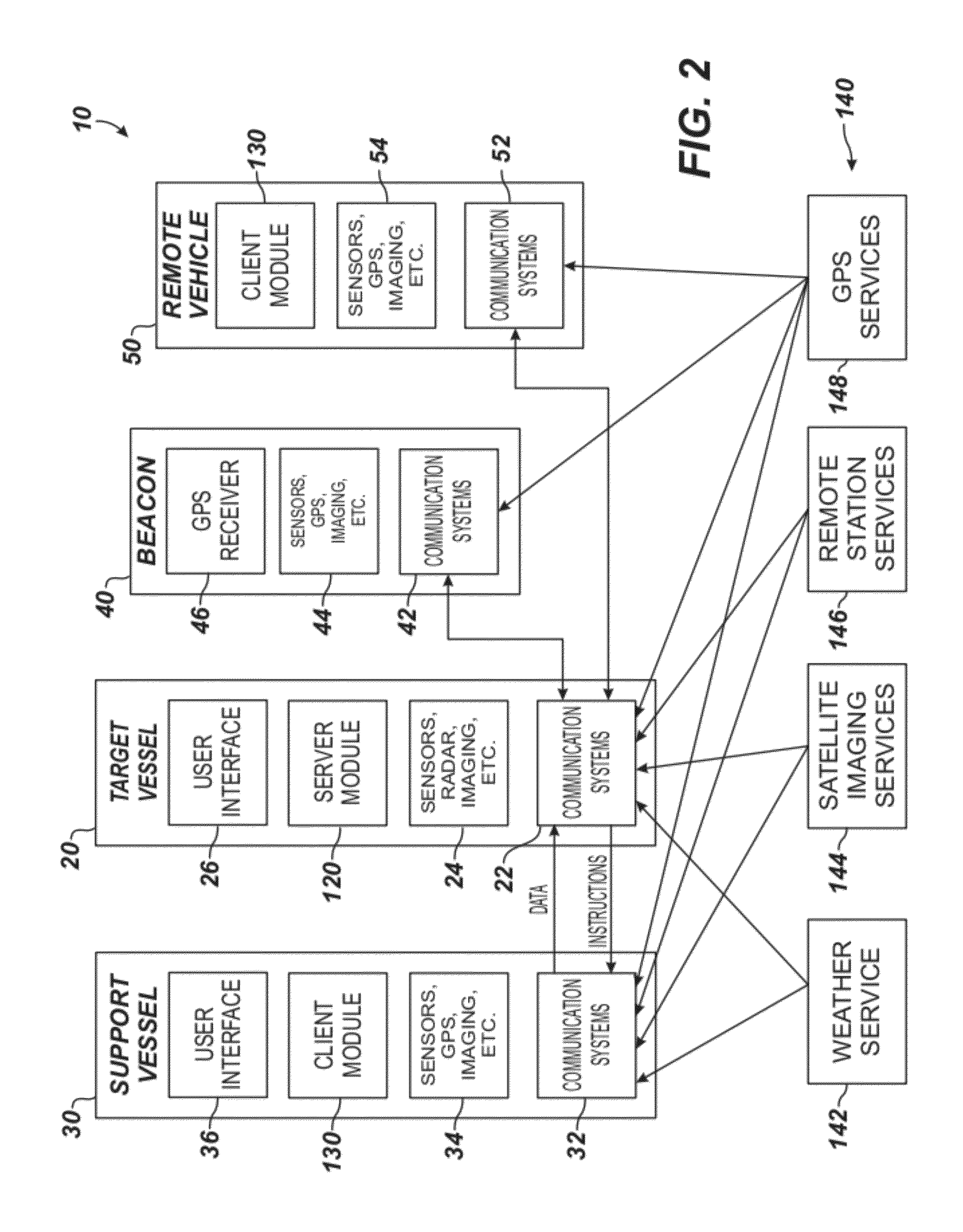
[0021]As noted previously, protecting attached, fixed, or stationary marine structures or marine structures with planned movements or routes from marine obstacles and impacts presents a significant challenge to drilling, production, and exploration operations in some marine regions, such as the arctic. To meet this challenge, operators on such a structure can use a marine threat monitoring and defense system 10 as schematically illustrated in FIG. 1. The monitoring system 10 protects a target marine structure 20 in a region, such as the arctic, having floating and / or submerged objects that move in the ocean and threaten the structure 20.

[0022]In general, the target marine structure 20 can be a production vessel, a production platform, a drilling ship, a wellhead, a riser, a seismic survey vessel, or other marine structure used in drilling, production, or exploration operations at sea. The structure 20 can be floating or fixed and can be permanen...


PUM


Abstract

A marine threat monitoring and defense system and method protects a target vessel in icy or other marine regions. The system uses communications, user interfaces, and data sources to identify marine obstacles (e.g., icebergs, ice floes, pack ice, etc.) near a target vessel performing set operations (e.g., a stationed structure performing drilling or production operations or a seismic survey vessel performing exploration operations with a planned route). The system monitors positions of these identified marine obstacles over time relative to the target vessel and predicts any potential threats. When a threat is predicted, the system plans deployment of support vessels, beacons, and the like to respond to the threat. For example, the system can direct a support vessel to divert the path or break up ice threatening the target vessel.

Description

CROSS-REFERENCE TO RELATED APPLICATIONS[0001]This application claims the benefit of U.S. Provisional Appl. No. 61 / 488,879, filed 23 May 2011, which is incorporated herein by reference in its entirety and to which priority is claimed.BACKGROUND[0002]Oil and gas production operations in new regions, such as the arctic, have dramatically increased over the past few years. This increasing activity makes it more likely that fixed or floating production platforms, drill ships, and other structures will be used in these regions. A concern for these types of structures in such regions is potential for damage caused by objects that are uncontrolled and floating or submerged in the water, such as flotsam, jetsam, debris, icebergs, ice floes, and other threats (“marine obstacles”). In icy regions, for example, large icebergs and strong ice floes can pass through survey, production, and drilling areas. Although production vessels may be designed to handle some impacts from such marine obstacles...

Claims


Application Information

Patent Timeline
Patent Type & Authority Applications(United States)
IPC IPC(8): G06F17/00
CPCB63B43/18G08G3/02B63J2099/006B63B2211/06B63B35/086G01S13/937
Inventor GAGLIARDI, JOSEPH R.FLYNN, DESGRANT, JOHN
Owner CONCEPT SYST
Why Eureka
Try Eureka