
Methods of interconnecting thin film solar cells

a technology of solar cells and thin films, applied in the direction of photovoltaics, electrical equipment, semiconductor devices, etc., can solve the problems of monolithic integration structure of modules, unbreakable, and light weight of flexible modules, and unlike glass based si solar modules

Inactive Publication Date: 2012-12-20
SOLOPOWER
View PDF3 Cites 177 Cited by
  • Summary
  • Abstract
  • Description
  • Claims
  • Application Information

AI Technical Summary

Benefits of technology

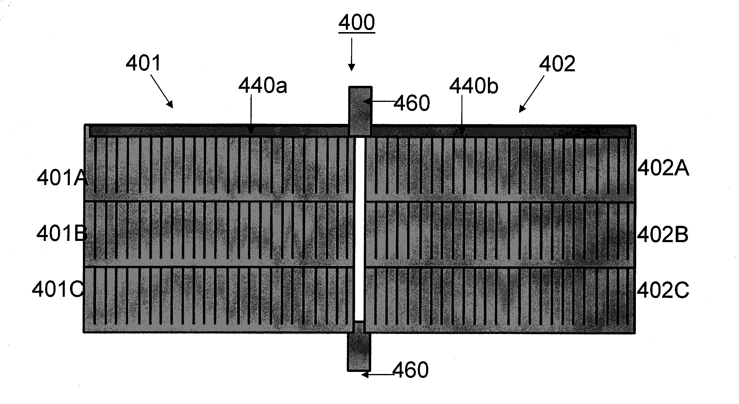
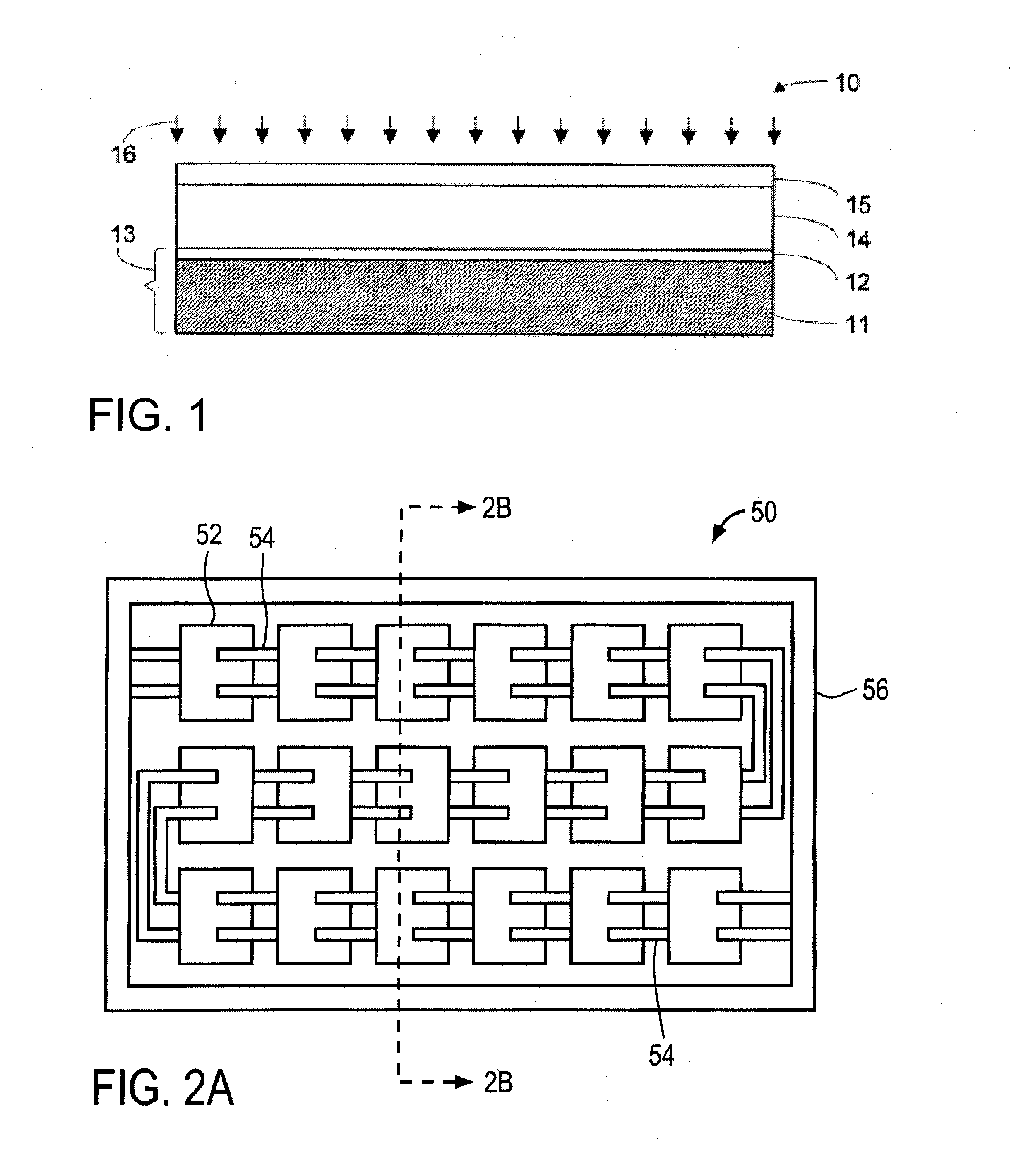
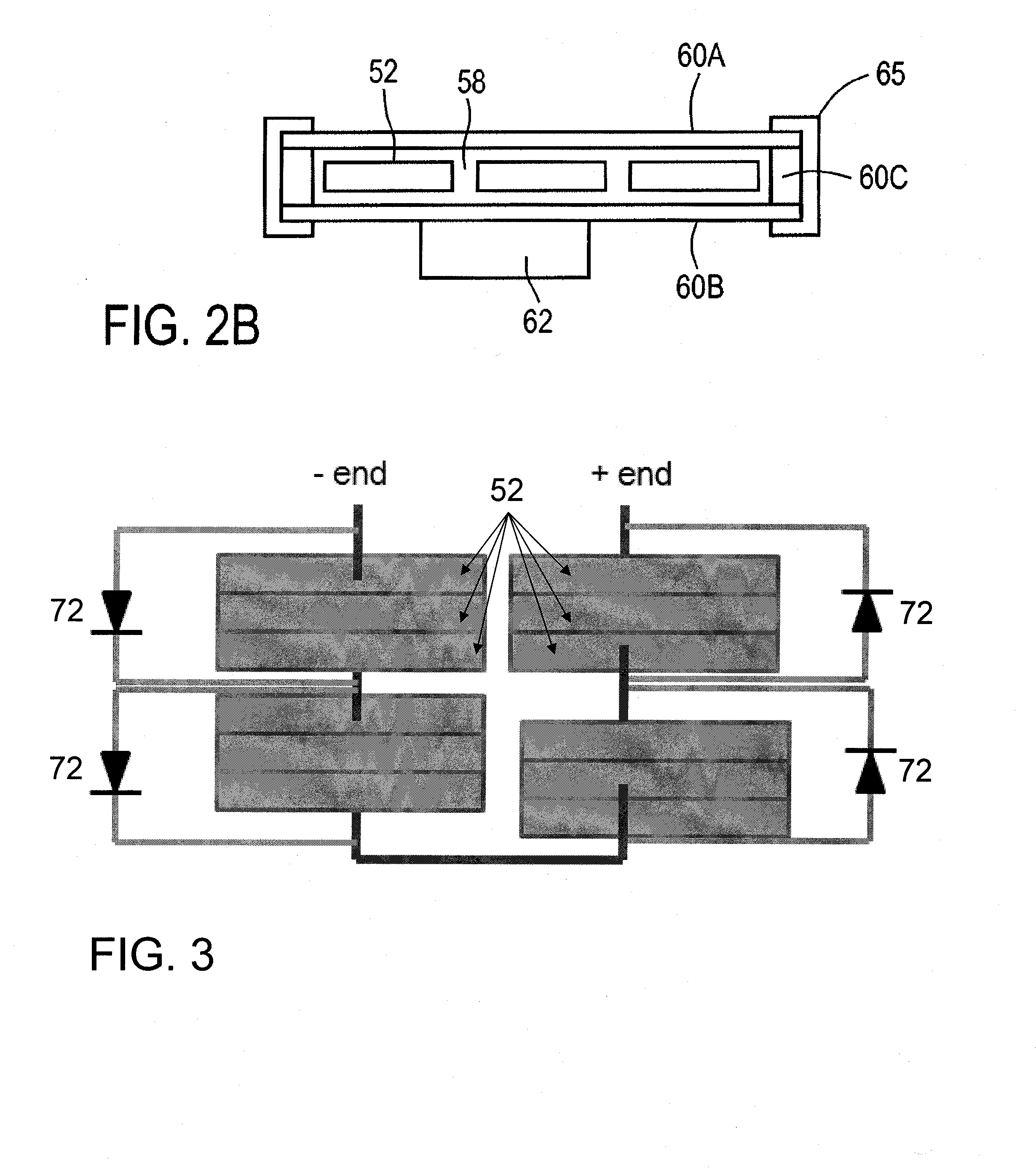
[0017]In one implementation, the first group of solar cells in the photovoltaic module comprises a first solar cell connected in series to a second solar cell, and the second group of solar cells in the photovoltaic module comprises a first solar cell connected in series to a second solar cell. The bypass diode may be disposed over the second surface of the second group of solar cells. The bypass diode may be connected to the first and second groups of solar cells such that the bypass diode inhibits reverse bias of the first or second group of solar cells when one or more cells of the first or second groups of solar cells are reverse biased. The second interconnection member may be configured to direct current through the first or second group of solar cells.

Problems solved by technology

These modules are monolithically integrated structures.
Flexible modules are light weight, and unlike the standard glass based Si solar modules, are unbreakable.
Therefore, packaging and transportation costs for the manufactured flexible modules are much lower than for solar cell or module structures formed on glass that are not flexible and are easily damaged by mishandling.
However, manufacture of flexible module structures is challenging in respects that are different from solar cell and module structures formed on glass that are not flexible.
Further, while glass handling equipment used in glass based PV module manufacturing is fully developed by many equipment suppliers, handling of flexible sheets cannot be carried out using such standard equipment, and different equipment is required.
Further, requirements are different for the flexible sheets that constitute the various layers in the flexible module structure.
Such reverse biasing of individual cells may cause breakdown of that cell and its overheating, and degradation of the overall module output.
However, bypass diodes are expensive, and it is not practical to place so many bypass diodes in a junction box outside the module package.

Method used


Image

  • Methods of interconnecting thin film solar cells
  • Methods of interconnecting thin film solar cells
  • Methods of interconnecting thin film solar cells

Examples


Embodiment Construction

[0039]The embodiments described herein provide methods of interconnecting solar cells or photovoltaic (PV) cells. Embodiments will be described with reference to specific interconnected solar cell configurations or arrays. However, it will be appreciated that embodiments of the present invention may be practiced with other configurations without departing from the scope of the present invention.

[0040]Embodiments described herein provide module structures and methods of manufacturing rigid or flexible PV modules employing thin film solar cells fabricated on flexible substrates, preferably on flexible metallic foil substrates. The solar cells may be Group IBIIIAVIA compound solar cells fabricated on thin stainless steel or aluminum alloy foils. The modules may each include a moisture resistant protective shell within which the interconnected solar cells or cell strings are packaged and protected. The protective shell may comprise a moisture barrier top protective sheet through which t...


PUM


Abstract

A photovoltaic module comprises a first group of solar cells; a second group of solar cells; a first interconnection member extending across a first surface of the first group of solar cells and across a first surface of the second group of solar cells to connect the first and second groups of solar cells in parallel; and a second interconnection member extending across a second surface of the first group of solar cells and across a second surface of the second group of solar cells.

Description

RELATED APPLICATIONS[0001]This application is a continuation-in-part of U.S. patent application Ser. No. 13 / 163,485, filed on Jun. 17, 2011, entitled “CIGS BASED THIN FILM SOLAR CELLS HAVING SHARED BYPASS DIODES” which is hereby incorporated by reference in its entirety.BACKGROUND[0002]1. Field of the Inventions[0003]Embodiments of the present invention generally relate to photovoltaic or solar module design and fabrication and, more particularly, to modules utilizing thin film solar cells.[0004]2. Description of the Related Art[0005]Solar cells are photovoltaic (PV) devices that convert sunlight directly into electrical energy. Solar cells can be based on crystalline silicon or thin films of various semiconductor materials, that are usually deposited on low-cost substrates, such as glass, plastic, or stainless steel.[0006]Thin film based photovoltaic cells, such as amorphous silicon, cadmium telluride, copper indium diselenide or copper indium gallium diselenide based solar cells, ...

Claims


Application Information

Patent Timeline
Patent Type & Authority Applications(United States)
IPC IPC(8): H01L31/05H01L31/18
CPCY02E10/50H01L31/0504H01L31/0201
Inventor PINARBASI, MUSTAFAMETIN, BURAK
Owner SOLOPOWER
Learn More