
Label manufacturing device and label printer

a manufacturing device and label printer technology, applied in the direction of identification means, instruments, paper/cardboard articles, etc., can solve the problems of affecting the work efficiency of workers, requiring a lot of effort to remove the adhesive agent attached to workers' hands, clothing and peripheral equipment,

Inactive Publication Date: 2012-12-20
LINTEC CORP
View PDF4 Cites 7 Cited by
  • Summary
  • Abstract
  • Description
  • Claims
  • Application Information

AI Technical Summary

Benefits of technology

The invention provides a label manufacturing device and label printer that allow for the free combination of a base material sheet and adhesive agent used in a label sheet. This eliminates the need for workers to manually clean up and remove adhesive agent when switching base material sheets and adhesive agents. The device includes a base material feeder, printing unit, and attachment unit that attaches the adhesive film onto the base material sheet. The printing unit prints on the base material sheet while the attachment unit attaches the adhesive film onto the base material sheet. A second release liner may be peeled off when needed. The label printer includes a plate cylinder and impression cylinder that transfer the base material sheet and adhesive film while printing and adhesion occur. The technical effect of the invention is the simplification of the label manufacturing and printing process, reducing workload for workers and improving efficiency.

Problems solved by technology

However, the former of the above two devices requires changes in combinations of types of a base material sheet and an adhesive agent depending on a purpose and intended use because the device prints a web laminated beforehand with an adhesive agent layer on a base material sheet, forcing those in the printing industry offering this type of printing to own a stockpile of webs that matches the number of the combinations.
Though the latter is capable of switching base material sheets and adhesive agents, clean-up of an adhesive agent feeding head and the like using solvent is necessary when switching, thus causing workers significant workloads.
Another problem is that it takes quite an effort to remove adhesive agent attached on a worker's hands, clothing and peripheral equipment and the like.

Method used


Image

  • Label manufacturing device and label printer
  • Label manufacturing device and label printer
  • Label manufacturing device and label printer

Examples


Embodiment Construction

)

[0017]A label manufacturing device and label printer according to the invention will be described below by reference to exemplary embodiments.

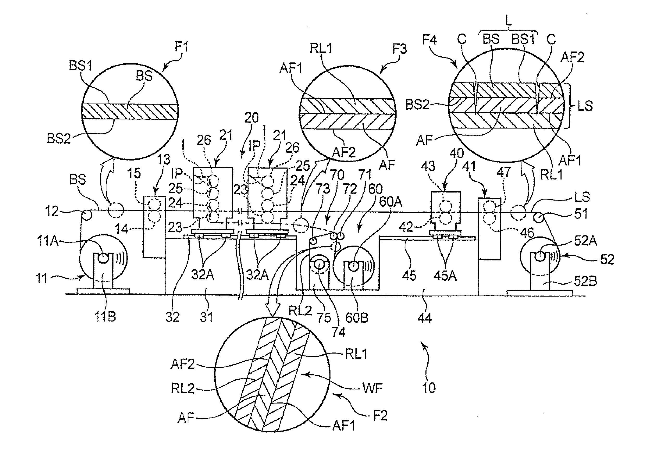
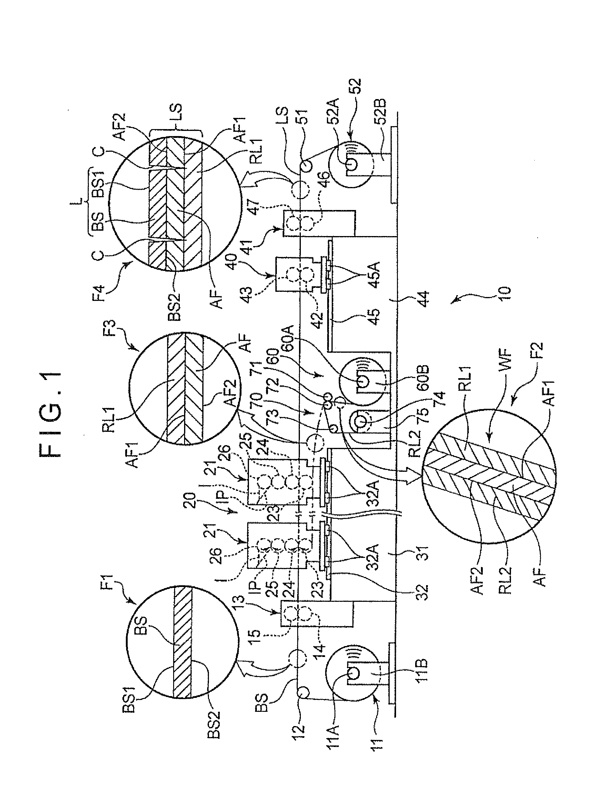
[0018]FIG. 1 schematically shows a configuration of a label manufacturing device 10 according to an exemplary embodiment of the invention, which is provided with a label printer 20 (a printing unit).

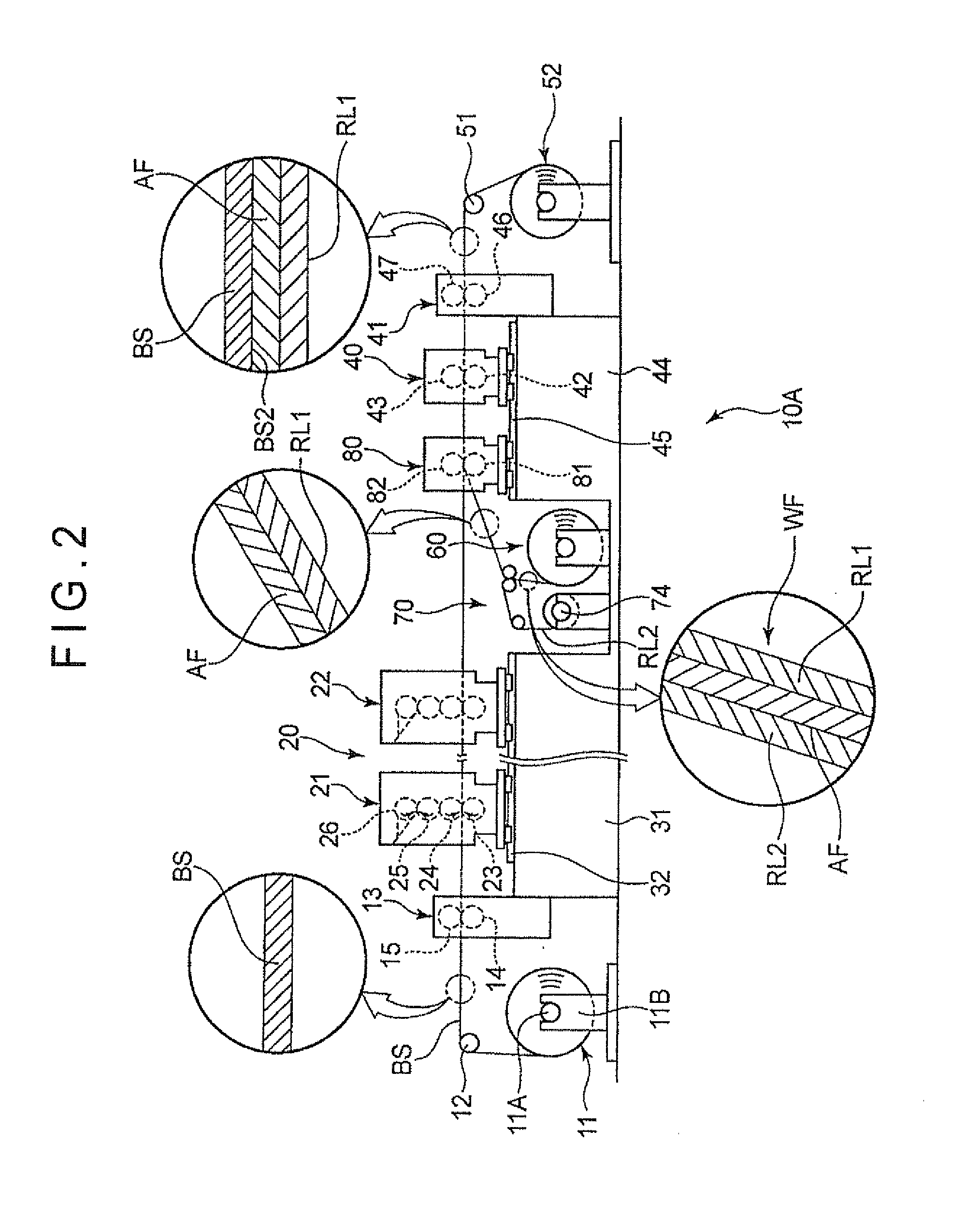
[0019]In summary, the label manufacturing device 10 includes: a base material supplying unit 11 from which a belt-shaped base material sheet BS is pulled up; a guide roller 12 that guides the base material sheet BS toward a feeding drive unit 13; and the label printer 20 to which the base material sheet BS is supplied. On the other hand, a belt-shaped adhesive film AF that enables adhesion of both sides and is temporarily attached with a first release liner RL1 on an adhered attachment surface (a first surface) AF1 (an upper surface in an expanded view F3 of FIG. 1) is supplied to the label printer 20 via a peeling unit 70 (a peeling unit) from an...


PUM

PropertyMeasurementUnit
adhesiveaaaaaaaaaa
adhesionaaaaaaaaaa
colorsaaaaaaaaaa

Abstract

A base material sheet is fed from a base material supplying unit by a feeding drive unit. A raw film made up of an adhesive film temporarily attached with a first and release liner and a second release liner is supplied from an adhesive film supplying unit and the second release liner is peeled off from the adhesive film by a peeling unit. A label printer prints on the base material sheet and attaches the adhesive film onto the base material sheet. A label sheet that includes the base material sheet, the adhesive film and the first release liner is supplied to a cutter. After a cut line corresponding to a shape of a label is provided on the base material sheet by the cutter, the base material sheet is further transferred by a guide roller and is wound up by a product winding unit.

Description

TECHNICAL FIELD[0001]The present invention relates to a label manufacturing device to produce label sheets with a triple layered structure having a base material sheet on which printing is made, an adhesive agent layer and a release liner, as well as a label printer to print on the label sheets with the triple layered structure of the base material sheet, the adhesive agent layer and the release liner.BACKGROUND ART[0002]Conventionally, a device to print on a base material sheet on which an adhesive agent layer is provided in advance (e.g., Patent Literature 1) and a device to apply an adhesive agent onto a printed base material sheet (e.g., Patent Literature 2) are known as such a label manufacturing device as the above.CITATION LISTPatent Literatures[0003]Patent Literature 1: JP-1995-35104B2[0004]Patent Literature 2: JP-A-2002-1845SUMMARY OF THE INVENTIONProblem(s) to be Solved by the Invention[0005]However, the former of the above two devices requires changes in combinations of t...

Claims


Application Information

Patent Timeline
Patent Type & Authority Applications(United States)
IPC IPC(8): B32B37/02B32B38/14B32B38/10B32B37/12
CPCY10T156/1705B31D1/027B31D1/02G09F3/00
Inventor KOBAYASHI, KENJI
Owner LINTEC CORP
Learn More