Waste heat recovery structure for steel making electric arc furnaces, steel making electric arc furnace facility, and waste heat recovery method for steel making electric arc furnaces

a technology of waste heat recovery structure and steel making electric arc furnace, which is applied in the direction of steam engine plants, machines/engines, metal processing, etc., can solve the problems of inconvenient steam turbine operation, and reduced steam generation amount, so as to minimize the number of running furnaces. , the effect of reducing the number of changes over tim

Active Publication Date: 2012-12-20
JP STEEL PLANTECH CO
View PDF4 Cites 14 Cited by
  • Summary
  • Abstract
  • Description
  • Claims
  • Application Information

AI Technical Summary

Benefits of technology

[0023]According to a third aspect of the present invention, there is provided a waste heat recovery structure for a plurality of steel making electric arc furnaces, which recovers waste heat as saturated steam from exhaust gas discharged from the steel making electric arc furnaces and turns the saturated steam into superheated steam by subsequent heating, the structure comprising: a first exhaust gas flow path provided to each of the steel making electric arc furnaces to discharge exhaust gas thereinto; a waste heat boiler disposed on the first exhaust gas flow path and configured to recover waste heat as saturated steam from exhaust gas; a steam accumulator configured to store steam formed by confluence of saturated steam parts, each generated by the waste heat boiler; a steam super heater configured to turn steam, which has been stored in the steam accumulator, into superheated steam by heating; a second exhaust gas flow path configured to lead exhaust gas, which has been treated with waste heat recovery in the waste heat boiler, to the steam super heater to use it for superheating saturated steam; and an operation section configured to operate the steel making electric arc furnaces to sequentially perform their running operations by staggering them with a predetermined deviation time, wherein the operation section sets the deviation time to minimize changes over time in the number of running furnaces of the steel making electric arc furnaces.
[0024]According to a fourth aspect of the present invention, there is provided a waste heat recovery method for a plurality of steel making electric arc furnaces, by use of a waste heat recovery structure that includes a first exhaust gas flow path provided to each of the steel making electric arc furnaces to discharge exhaust gas thereinto; a waste heat boiler disposed on the first exhaust gas flow path and configured to recover waste heat as saturated steam from exhaust gas; a steam accumulator configured to store steam formed by confluence of saturated steam parts, each generated by the waste heat boiler; a steam super heater configured to turn steam, which has been stored in the steam accumulator, into superheated steam by heating; and a second exhaust gas flow path configured to lead exhaust gas, which has been treated with waste heat recovery in the waste heat boiler, to the steam super heater to use it for superheating saturated steam, the method comprising: operating the steel making electric arc furnaces to sequentially perform their running operations by staggering them with a predetermined deviation time, wherein the deviation time is set to minimize changes over time in the number of running furnaces of the steel making electric arc furnaces.

Problems solved by technology

As the exhaust gas temperature undergoes a lot of fluctuations like this, the steam generation amount becomes inconstant and so does the recovered steam amount.
If the recovered steam amount is inconstant, the steam turbine supplied with the recovered steam suffers a decrease in electric power generation, thereby making it difficult for the steam turbine to conduct a steady running operation.
Further, the steam recovered by a waste heat boiler is saturated steam and so has a lower utility potential as it is.
However, in the case of the method disclosed in Patent Document 2, it is necessary to use another heat source, such as a fossil fuel, to turn the saturated steam into the superheated steam, thereby lowering the energy economical efficiency.

Method used


Image

  • Waste heat recovery structure for steel making electric arc furnaces, steel making electric arc furnace facility, and waste heat recovery method for steel making electric arc furnaces
  • Waste heat recovery structure for steel making electric arc furnaces, steel making electric arc furnace facility, and waste heat recovery method for steel making electric arc furnaces
  • Waste heat recovery structure for steel making electric arc furnaces, steel making electric arc furnace facility, and waste heat recovery method for steel making electric arc furnaces

Examples


first embodiment

[0047]At first, an explanation will be given of a first embodiment.

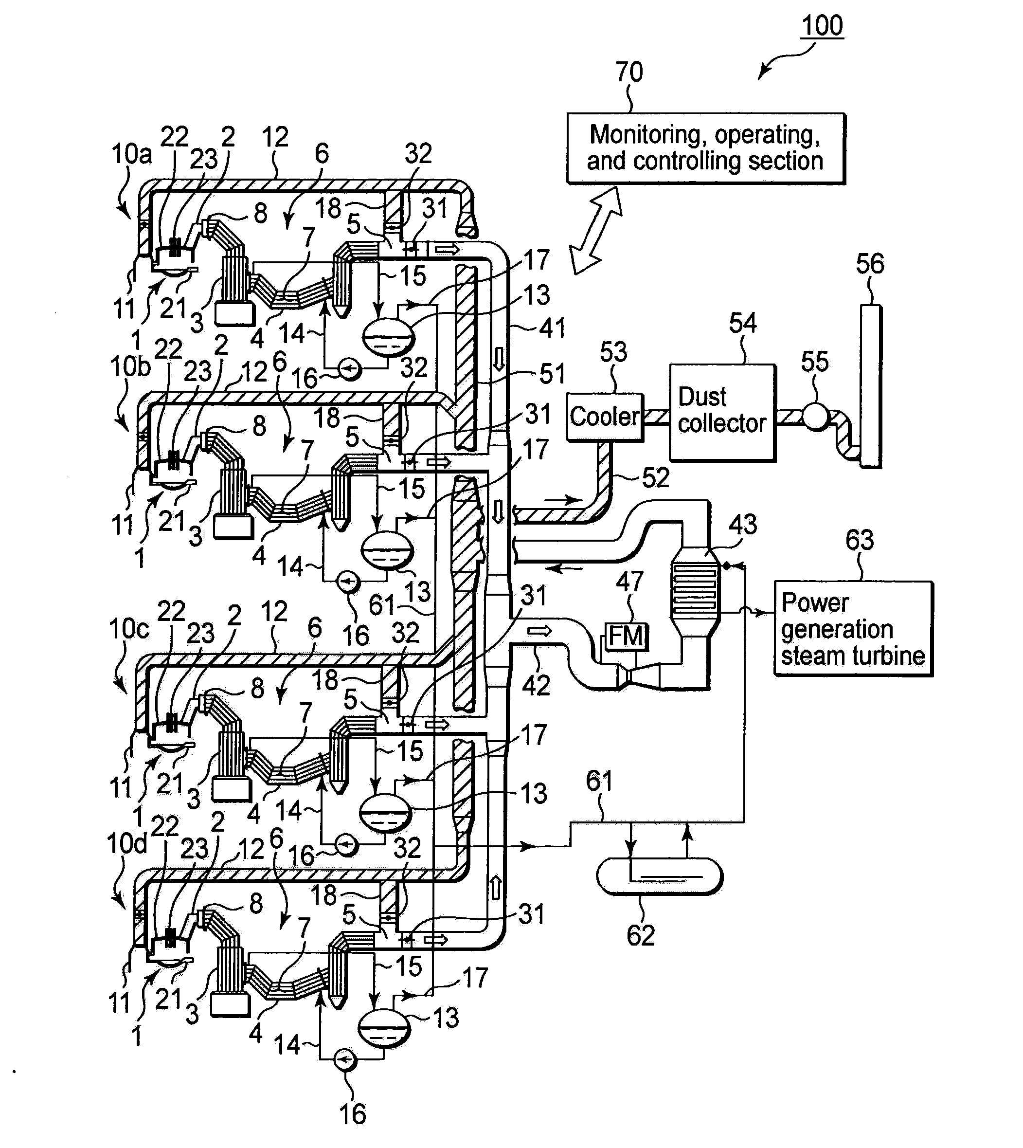
[0048]FIG. 1 is a schematic constitutive view showing a steel making electric arc furnace facility equipped with a waste heat recovery structure for steel making electric arc furnaces according to an embodiment of the present invention. This steel making electric arc furnace facility 100 includes four electric arc furnace units 10a, 10b, 10c, and 10d. These electric arc furnace units 10a to 10d are installed in a steel making factory (not shown), and each of them includes a steel making electric arc furnace 1 and an exhaust gas duct 2 connected to the steel making electric arc furnace 1. Exhaust gas having a high temperature is discharged from the steel making electric arc furnace 1 and flows into the exhaust gas duct 2. The exhaust gas duct 2 is connected to a front side water-cooled duct 4, and the front side water-cooled duct 4 is connected to a combustion chamber 3 for burning the exhaust gas. The combustion cham...

second embodiment

[0090]In the second embodiment, the steel making electric arc furnace facility 100 shown in FIG. 1, which is designed as explained in the first embodiment, is used, while the running operation timings of a plurality of steel making electric arc furnaces are controlled with a high degree of accuracy.

[0091]In this embodiment, the monitoring, operating, and controlling section 70 of the steel making electric arc furnace facility 100 switches the exhaust gas flow paths with reference to, e.g., the temperature at the outlet port of the waste heat boiler 6. Further, the monitoring, operating, and controlling section 70 controls the four steel making electric arc furnaces 1 to sequentially perform their running operations by staggering them with a predetermined “deviation time”. The “deviation time” used for this is set to minimize the changes over time in the number of running furnaces of the four steel making electric arc furnaces 1, and to maximize the value obtained by temporally integ...


PUM

PropertyMeasurementUnit
temperatureaaaaaaaaaa
exhaust gas temperatureaaaaaaaaaa

Abstract

A waste heat recovery structure includes a first exhaust gas flow path provided to each of steel making electric arc furnaces to discharge exhaust gas thereinto; a waste heat boiler disposed on the first exhaust gas flow path to recover waste heat as saturated steam from exhaust gas; a steam accumulator configured to store steam formed by confluence of saturated steam parts, each generated by the waste heat boiler; a steam super heater configured to turn steam into superheated steam by heating; a second exhaust gas flow path configured to lead exhaust gas from the waste heat boiler to the steam super heater to use it for superheating; a third exhaust gas flow path configured to discharge exhaust gas from the waste heat boiler not through the steam super heater; and a switching device configured to switch flow paths between the second and third exhaust gas flow paths.

Description

TECHNICAL FIELD[0001]The present invention relates to a waste heat recovery structure for steel making electric arc furnaces, which recovers waste heat as saturated steam from exhaust gas discharged from the steel making electric arc furnaces and turns the steam into superheated steam by subsequent heating. The present invention further relates to a steel making electric arc furnace facility including such a waste heat recovery structure, and a waste heat recovery method for steel making electric arc furnaces.BACKGROUND ART[0002]A steel making electric arc furnace (which may be referred to as “electric furnace”) employs an intermittent running operation performed by use of cycles, each of which includes steps as follows. At first, a source material, such as iron scrap, reduced iron (DRI), hot briquette iron (HBI) prepared by processing the DRI at a high temperature, molten iron, or cold iron (ingot iron), is charged into the furnace. Then, an electrode is inserted into the electric ...

Claims


Application Information

Patent Timeline
Patent Type & Authority Applications(United States)
IPC IPC(8): F27D17/00C21C5/52
CPCC21C5/40C21C5/5294C21C2100/06F01K3/22F22B1/183F27D17/003F27D17/004F27D17/008F27D19/00Y02P10/265Y02P10/283Y02P10/216Y02P10/20Y02P10/25
Inventor WAKAHARA, KEIJIFUJIKURA, NOBUYUKIYAMAZAKI, MASANARIWATANABE, MASAYUKIOKUYAMA, YOSHINORI
Owner JP STEEL PLANTECH CO
Why Eureka
Try Eureka