Node equipment

a technology of nodes and equipment, applied in the field of nodes, can solve the problems of affecting all wavelengths, affecting the performance of wavelength division multiplexing optical transmission systems, and affecting the quality of signal light waves, so as to reduce the output power of excitation ld, reduce the cost, and reduce the gain saturation level

Inactive Publication Date: 2012-12-20
MITSUBISHI ELECTRIC CORP
View PDF2 Cites 11 Cited by
  • Summary
  • Abstract
  • Description
  • Claims
  • Application Information

AI Technical Summary

Benefits of technology

[0023]According to the present invention, it has the configuration as described above and includes the output level detecting unit for detecting the optical power level of the wavelength division multiplexing signals at the pre-stage of the optical cord, the input level detecting unit for detecting the optical power level of the wavelength division multiplexing signals at the post-stage of the optical cord, the deciding unit for making the abnormality decision of the loss of the optical power level through the optical cord from the optical power level detected by the output level detecting unit and from the optical power level detected by the input level detecting unit, and the control unit for controlling the optical attenuation of the optical attenuator unit in accordance with the abnormality decision result by the deciding unit. As a result, since it can prevent a transmitting-side optical amplifier unit from receiving a sharp level increase, it can ensure the signal quality of an Add wavelength. In addition, it can also reduce the gain saturation level of the transmitting-side optical amplifier unit, thereby being able to reduce the output power of the excitation LD used in the transmitting-side optical amplifier unit, and hence to reduce the cost.

Problems solved by technology

In addition, as a network becomes complicated, demands on the wavelength division multiplexing optical transmission system are growing.
However, as for a fault of the optical amplification functional unit for amplifying the wavelength division multiplexing signals as a whole or that of the wavelength multiplexing / demultiplexing functional unit, or a physical phenomenon such as nonlinear optical effects occurring in a transmission path connecting between two or more pieces of node equipment, they can sometimes affect all the wavelengths and degradation can sometimes occur in signal light waves having nothing to do with the fault.
When such an instantaneous optical power level reduction occurs, a signal receiver unit on the opposite side cannot maintain the signal quality and can cause an information loss.
Thus, it has a problem of affecting the signal quality of signal light waves with wavelengths other than those at the faulty spot when the optical connector is reinserted.

Method used


Image

  • Node equipment
  • Node equipment
  • Node equipment

Examples


embodiment 1

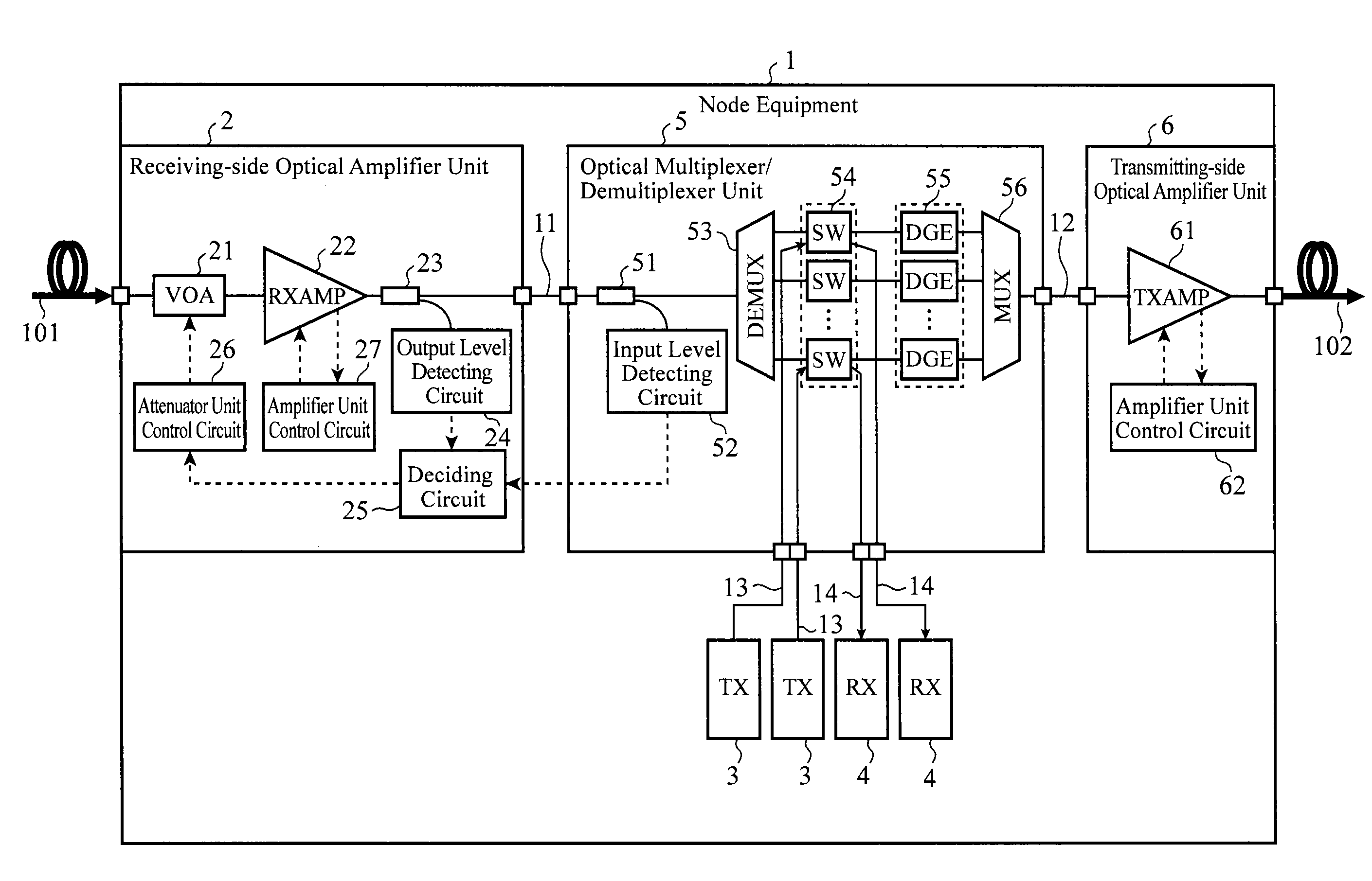
[0040]FIG. 1 is a block diagram showing a configuration of the node equipment 1 of the embodiment 1 in accordance with the present invention. Incidentally, a wavelength division multiplexing optical transmission system has a plurality of pieces of node equipment 1 connected via a transmission path.

[0041]As shown in FIG. 1, the node equipment 1 comprises a receiving-side optical amplifier unit 2, a plurality of signal transmitter units (TX) 3, a plurality of signal receiver units (RX) 4, an optical multiplexer / demultiplexer unit 5 and a transmitting-side optical amplifier unit 6.

[0042]The receiving-side optical amplifier unit 2 is a unit for compensating for the loss of a transmission path with respect to the optical power level of wavelength division multiplexing signals received from upstream node equipment (not shown) via a transmission path 101. The receiving-side optical amplifier unit 2 comprises a variable optical attenuator unit (VOA) 21, a receiving-side optical amplificatio...

embodiment 2

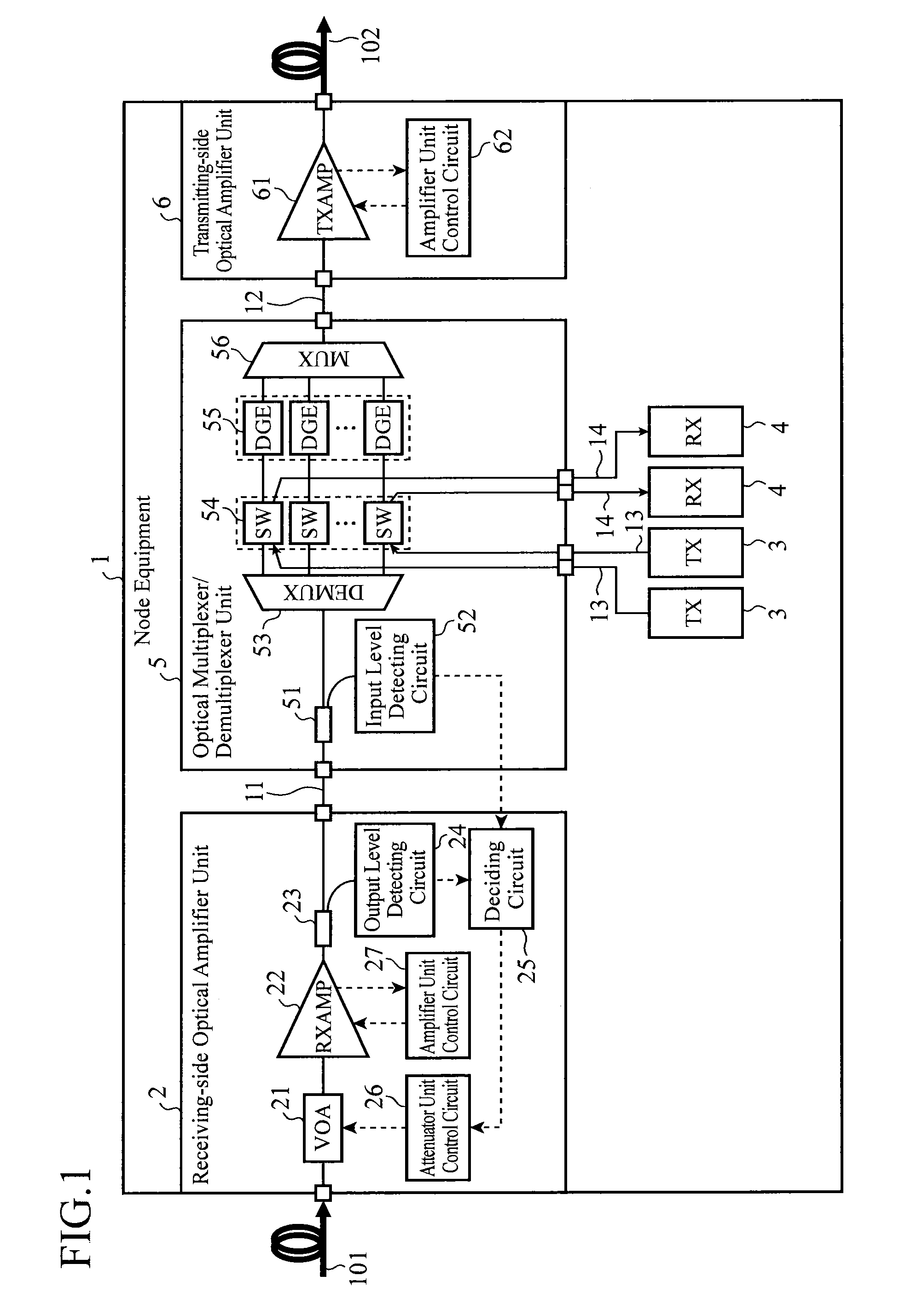
[0108]FIG. 8 is a block diagram showing a configuration of the node equipment 1 of an embodiment 2 in accordance with the present invention. Although the configuration of the node equipment 1 of the embodiment 2 shown in FIG. 8 is basically the same as that of the node equipment 1 of the embodiment 1 shown in FIG. 1, it differs in the processing contents of the deciding circuit 25 and amplifier unit control circuit 27. Only the different points will be described below.

[0109]Incidentally, as for the abnormality decision operation and normality decision operation of the node equipment 1 of the embodiment 2, since they are the same as the abnormality decision operation and normality decision operation of the node equipment 1 of the embodiment 1 shown in FIGS. 5 and 7, their description will be omitted.

[0110]When the deciding circuit 25 decides that the loss (L) of the optical power level is in the abnormal state, it notifies the amplifier unit control circuit 27 of that (abnormality de...

embodiment 3

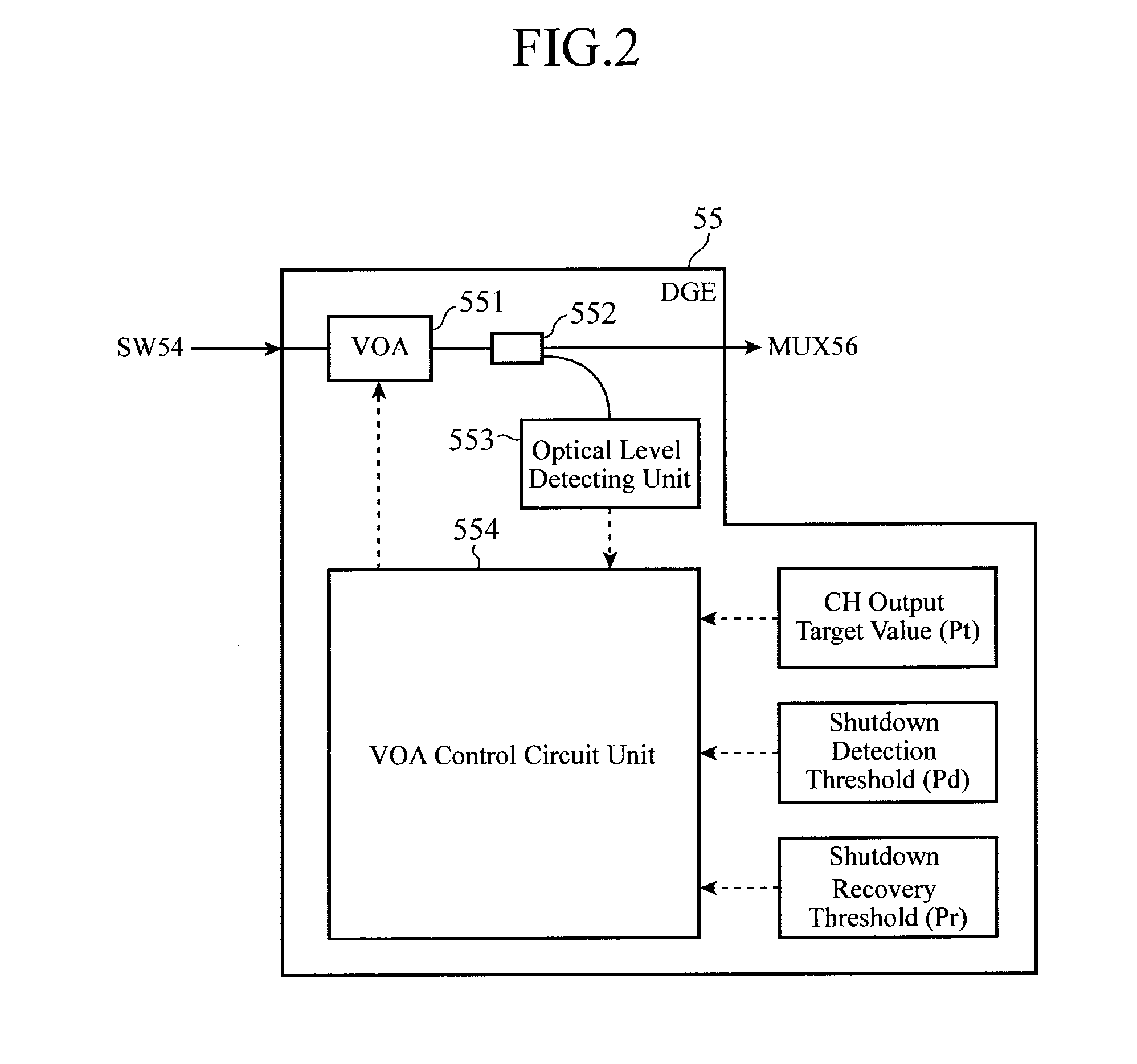
[0116]FIG. 10 is a diagram showing the node equipment 1 of the embodiment 3 in accordance with the present invention, and FIG. 11 is a diagram illustrating a control state transition of the VOA control circuit unit in the embodiment 3 in accordance with the present invention. The node equipment 1 of the embodiment 3 shown in FIG. 10 is configured by removing the deciding circuit 25 from the node equipment 1 of the embodiment 1 shown in FIG. 1 and by adding a deciding circuit (deciding unit) 57. Since the remaining components are the same, they are designated by the same reference numerals and their description will be omitted.

[0117]Incidentally, as for abnormality decision operation and normality decision operation of the node equipment 1 of the embodiment 3, since they are the same as the abnormality decision operation and normality decision operation of the node equipment 1 of the embodiment 1 shown in FIGS. 5 and 7 except that the deciding circuit 57 carries out the processing of...


PUM


Abstract

Node equipment 1, having optical attenuator unit 21 for optically attenuating wavelength division multiplexing signals received and optical multiplexer / demultiplexer unit 5 for performing optical multiplexing / demultiplexing of the wavelength division multiplexing signals received from the optical attenuator unit 21 via an optical cord 11, includes: output level detecting unit 24 for detecting the optical power level of the wavelength division multiplexing signals at a pre-stage of the optical cord 11; input level detecting unit 52 for detecting the optical power level of the wavelength division multiplexing signals at a post-stage of the optical cord 11; deciding unit 25 for deciding abnormality of the optical power level loss through the optical cord 11 from the optical power levels detected by the output level detecting unit 24 and input level detecting unit 52; and control unit 26 for controlling the optical attenuation of the optical attenuator unit 21 according to the abnormality decision result by the deciding unit 25.

Description

TECHNICAL FIELD[0001]The present invention relates to node equipment with functions of transmitting and multiplexing / demultiplexing wavelength division multiplexing signals, and particularly to node equipment that does not affect a service wavelength even if an unsuitable connection occurs in an optical connector in the node equipment.BACKGROUND ART[0002]A wavelength division multiplexing optical transmission system having a plurality of pieces of node equipment connected is an optical transmission communication system that increases the transmission capacity of signals transmitted through a single fiber by wavelength multiplexing signal light waves assigned to a plurality of wavelengths by using wavelength division multiplexing.[0003]The wavelength division multiplexing is a communication method that applies the fact that signal light waves with different wavelengths can exist independently, and can increase the transmission capacity easily by increasing the number of wavelengths t...

Claims


Application Information

Patent Timeline
Patent Type & Authority Applications(United States)
IPC IPC(8): H04J14/02H04B10/079H04B10/294
CPCH04B10/07955H04B10/2941H04J14/0221H04B10/294
Inventor SUEOKA, HIDEKI
Owner MITSUBISHI ELECTRIC CORP
Why Eureka
Try Eureka