Method for printing product features on a substrate sheet

a substrate sheet and product technology, applied in the field of products with printed product features, can solve the problems of insufficient filling and residual ink, affecting the perceived quality of images, and conventional printing techniques cannot readily provide the high-resolution objects necessary for synthetic image arrangement, and achieves the effect of improving dimensional tolerance and less artefacts

Active Publication Date: 2012-12-20
ROLLING OPTIKS AB
View PDF4 Cites 19 Cited by
  • Summary
  • Abstract
  • Description
  • Claims
  • Application Information

AI Technical Summary

Benefits of technology

[0026]It is a further advantage of the invention to provide a method and an arrangement for continuous processing of said products with printed product features arranged on a surface of a substrate sheet.
[0027]A yet further advantage is that the method and arrangement of the invention provides products having product features with improved dimensional tolerances and less artefacts, such as residual ink in-between product features, thereby enabling moiré magnification, allowing the generation of synthetic image devices and permitting the use of lenticular lenses. All of these require accurately printed product features since the use of them means that any artefact or deviation in dimension is magnified and possibly perceived by an observer.
[0028]Thus, the method and the arrangement of the present invention enable printing of product features on substrate sheets with printing accuracy with respect to lateral resolution, edge definition and dimensional tolerances in three dimensions that is not achievable with conventional printing techniques.
[0029]Embodiments of the invention are defined in the dependent claims. Other objects, advantages and novel features of the invention will become apparent from the following

Problems solved by technology

This colouring may be obtained by filling embossed cavities of the kind described above with ink, which is a challenging operation, in particular in large-scale production using for example the above mentioned roll-to-roll arrangement, since the embossed cavities, ranging from μm-sized cavities to cm-sized cavities, should all be equally filled without leaving residual ink on intermediate surfaces.
Incomplete filling and residual ink on intermediate surfaces may be detrimental for the perceived quality of the image.
However, these conventional printing techniques cannot readily provide the high-resolution objects necessary for the synthetic image arrangement, or other products comprising product features having the same requirements.

Method used


Image

  • Method for printing product features on a substrate sheet
  • Method for printing product features on a substrate sheet
  • Method for printing product features on a substrate sheet

Examples


Embodiment Construction

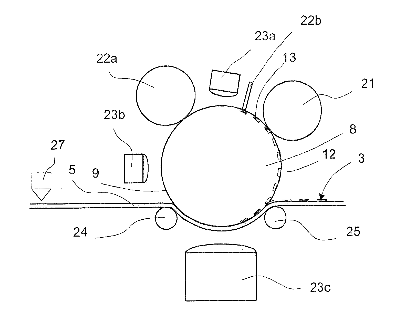
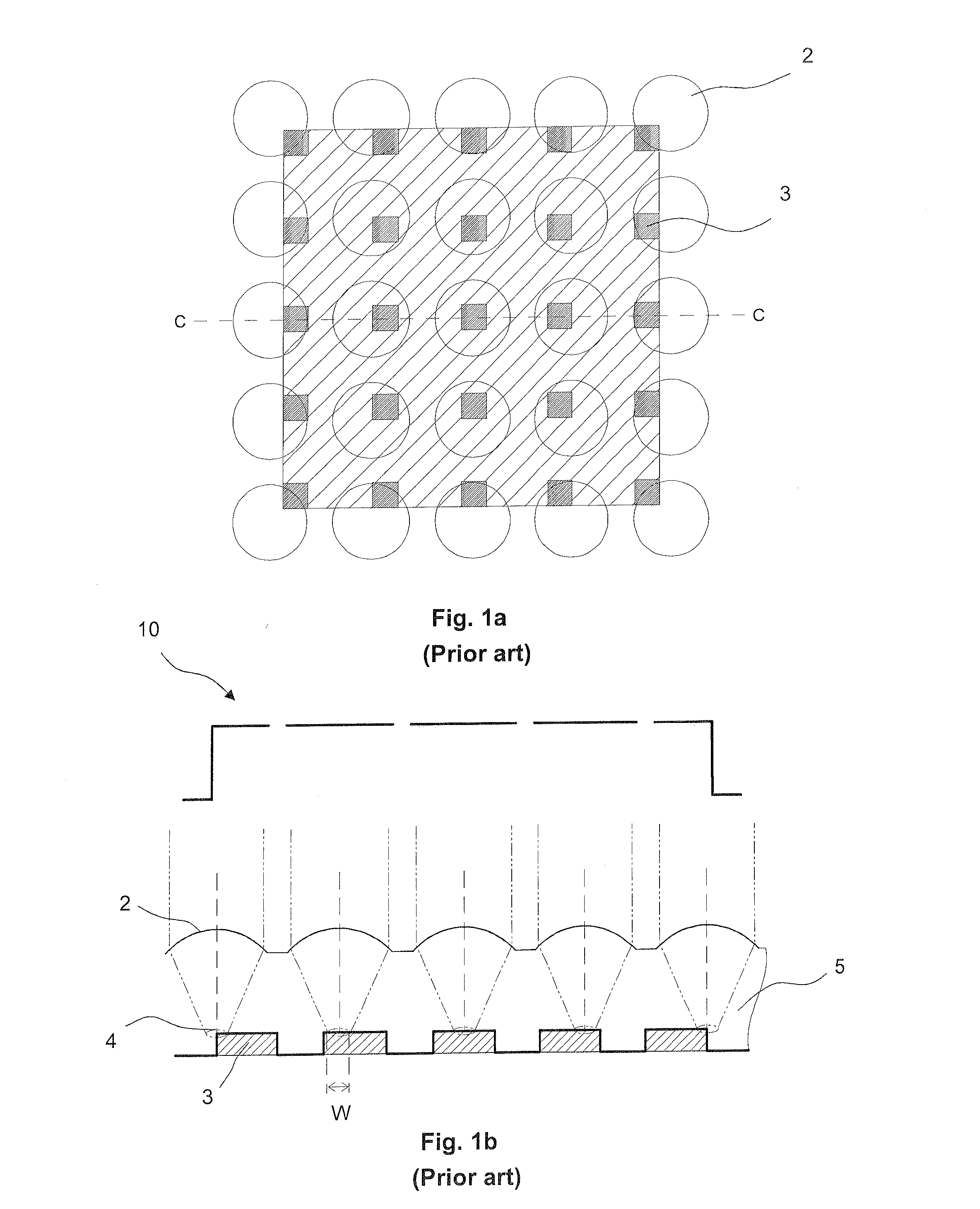
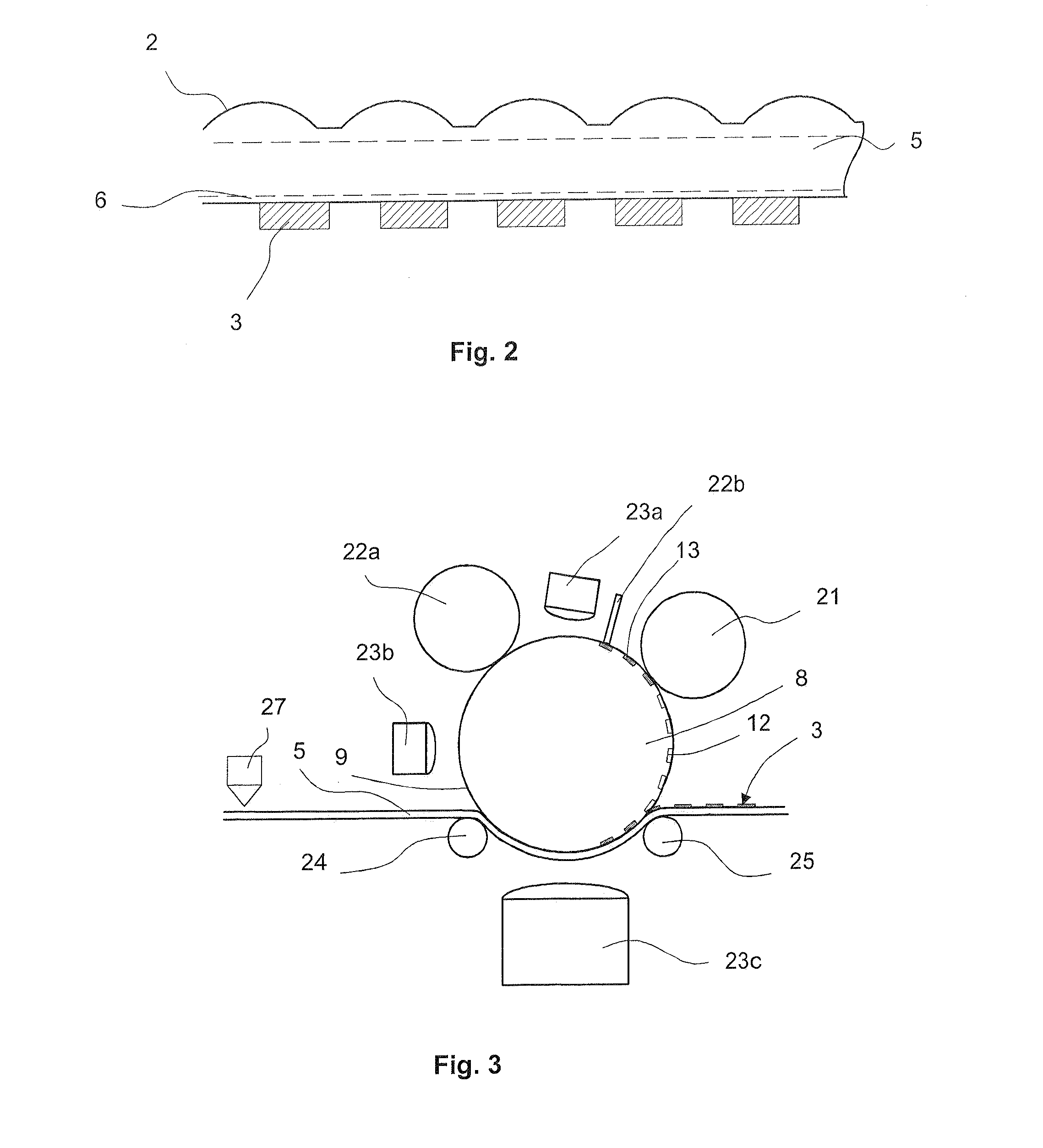
[0037]A product according to the invention comprises a body that in the product, or in an intermediate product, constitutes a substrate sheet with a limited thickness in relation to the extension in orthogonal directions thereof, and having product features arranged on, or in, one or both principal surfaces of the substrate sheet. By way of example, one embodiment of said product may comprise primary product features on a first side of a substrate sheet and secondary product features on the opposed side of the substrate sheet, the primary product features being associated with the secondary product features. Other embodiments of said product may comprise three or more sets of product features. In its most basic form the product comprises a substrate sheet with product features printed on only one surface thereof.

[0038]The product features can be used for different purposes, for example as structural and / or functional elements in a synthetic image device, as described above, or in ot...


PUM


Abstract

The present invention provides a method of producing a product comprising an array of product features (3) arranged on a surface (7) of a substrate sheet (5), and an arrangement for the production of such products. In this method curable compound (13) is filled into recesses of a matrix (8), pre-cured and then printed onto the substrate sheet (5), thereby forming printed product features (3). These printed product features (3) and additional product features (2) arranged on the opposed side of the substrate sheet (5) may form image objects and focusing elements, respectively, of a synthetic image device. By way of example a cast cure step can be used to form the additional product features (2). Preferably the production of the product is performed in a continuous roll-to-roll process.

Description

TECHNICAL FIELD OF THE INVENTION[0001]The present invention relates to products with printed product features arranged on a surface of a substrate sheet, and in particular to a method and an arrangement for producing such printed product features.BACKGROUND OF THE INVENTION[0002]In many applications an optical arrangement that provides a synthetic integral, possibly three dimensional, image for an observer is desired. FIGS. 1a and b schematically illustrate such an optical arrangement comprising an array of micro lenses 2 and an associated array of image objects 3 arranged on opposite sides of a transparent substrate sheet 5. In FIG. 1a, each micro lens 2 (circle) is arranged to magnify a small section 4 having width w of an associated image object 3 (square) so that a synthetic integral image 10 is perceived when viewed by an observer positioned at a distance from the array of micro lenses 2. The magnification effect, which in the field of art commonly is called “moiré-magnificatio...

Claims


Application Information

Patent Timeline
Patent Type & Authority Applications(United States)
IPC IPC(8): B05D5/00B05C1/00B05C13/00
CPCB29D11/00288B41P2200/30G02B3/0012B41M3/003B41M3/06B41F9/06G03F7/00G03F7/04H05K3/12B41F9/00G03F7/0002G03F7/004H05K3/1258
Inventor LUNDVALL, AXELENLUND, JOHANNESWEDIN, TOBIASGUSTAVSSON, FREDRIK
Owner ROLLING OPTIKS AB
Why Eureka
Try Eureka