Wireless communication system, communication device, program, and integrated circuit
- Summary
- Abstract
- Description
- Claims
- Application Information
AI Technical Summary
Benefits of technology
Problems solved by technology
Method used
Image

Examples
first embodiment
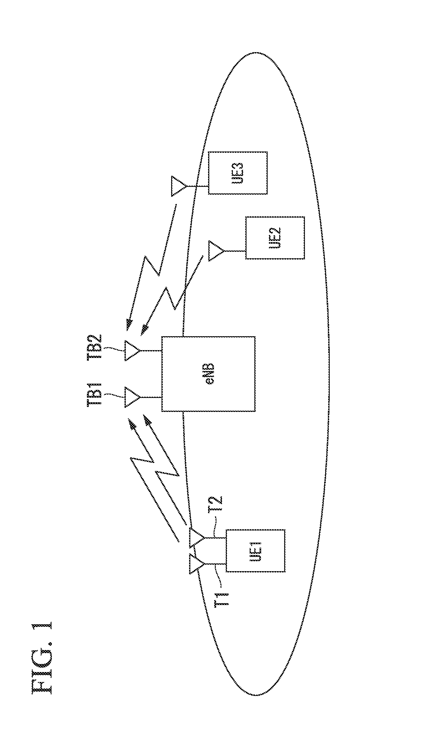
[0062]Hereinafter, embodiments of the present invention will be described with reference to the drawings. FIG. 1 is a conceptual diagram of a wireless communication system according to the first embodiment of the present invention.
[0063]In FIG. 1, a base station device eNB mutually performs wireless communication with a plurality of terminal devices UE1, UE2, and UE3 using downlink and uplink. Each of the base station device eNB and the plurality of terminal devices UE1, UE2, and UE3 is a device having a function of a transceiver. However, in description of the following embodiments, the case in which each of the plurality of terminal devices UE1, UE2, and UE3 transmits a data signal to the base station device eNB through the uplink will be described. Thus, in the meaning of a receiving side and a transmitting side of the data signal, the terminal device is referred to as a transmitting device and the base station device eNB is referred to as a receiving device. Therefore, although ...
second embodiment
[0176]In the second embodiment, a transmitting device is designated as a terminal device UE1 that performs MIMO transmission by multiple antennas (see FIG. 1) and the receiving device is designated as a base station device eNB2. A configuration example in which convergence characteristics are improved by configuring component encoders within a turbo encoding section in different convergence lengths in an environment in which the convergence characteristics of an iterative process in turbo equalization are bad such as when the encoding rate and / or multi-value modulation are high and a correlation value between antennas is high when the receiving device uses the iterative process such as the turbo equalization will be described using FIG. 10.
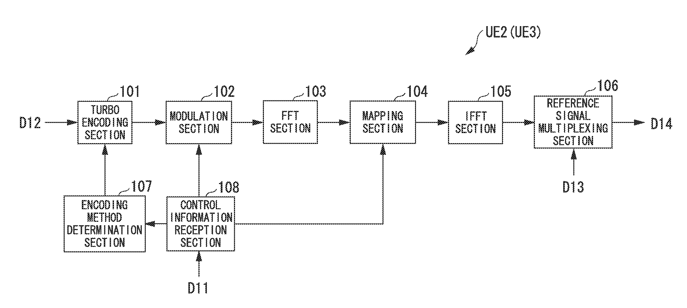
[0177]FIG. 10 is a block diagram illustrating a configuration example of a terminal device UE1, which is a transmitting device, according to the second embodiment. The terminal device UE1 includes a turbo encoding section 701, a serial / parallel (S...
third embodiment
[0256]In the third embodiment, a transmitting device performs transmission by multiple antennas, and allocates subcarriers having a high propagation gain to each antenna. When only some subcarriers overlap and a receiving device uses an iterative process such as turbo equalization, convergence characteristics are improved by configuring component encoders within a turbo encoding section in different convergence lengths in an environment in which convergence characteristics of the iterative process in the turbo equalization are bad such as when an encoding rate and / or multi-value modulation is high and when a correlation value between antennas is high. This configuration example will be described using FIG. 16. FIG. 16 is a diagram illustrating a configuration example of a receiving device of a base station device eNB3 according to this embodiment.
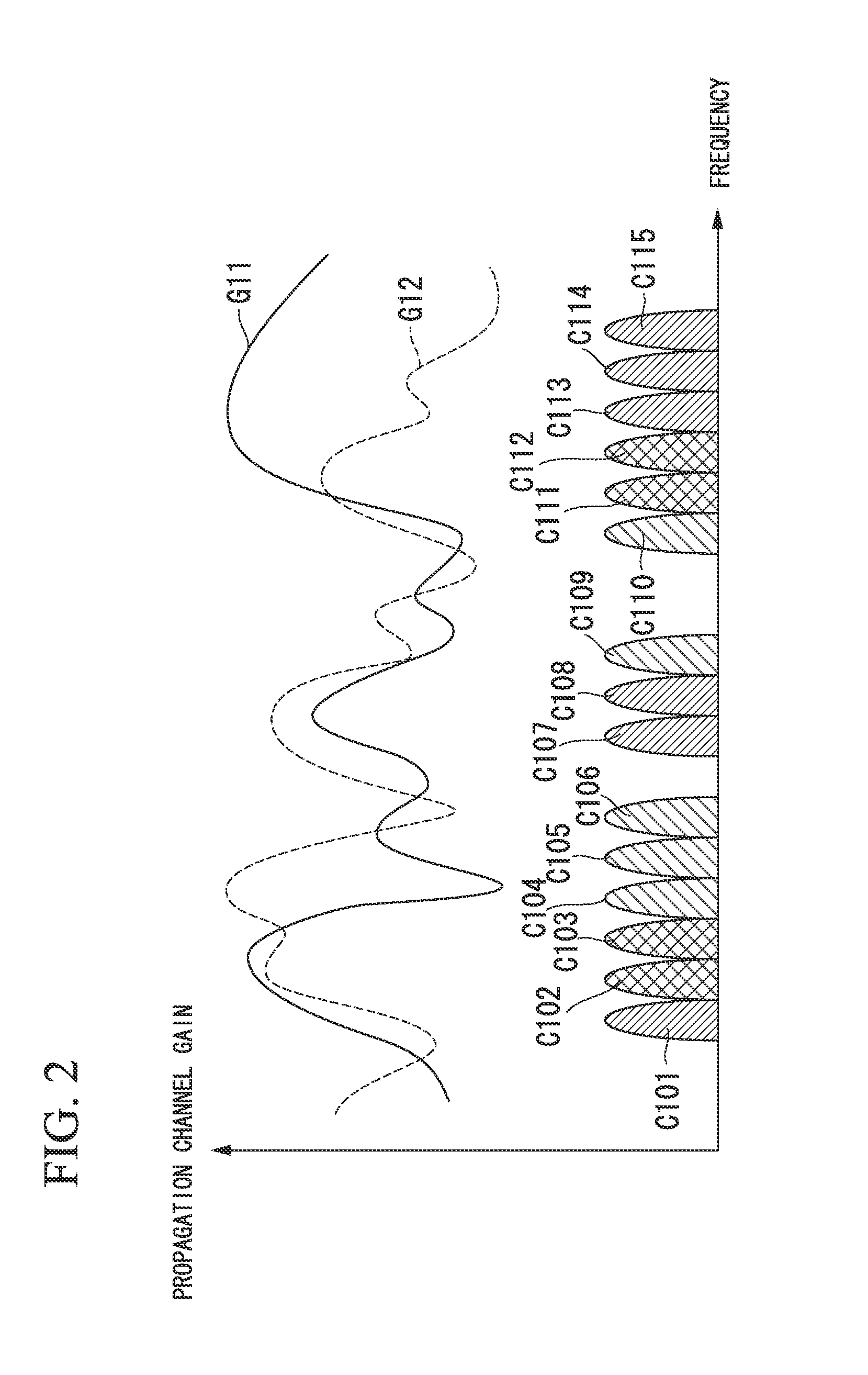
[0257]FIG. 15 illustrates an example in which bands are allocated to each antenna of this embodiment. Although the same band is allocated ...
PUM
 Abstract
Description
Claims
Application Information