

Vehicle brake apparatus
- Summary
- Abstract
- Description
- Claims
- Application Information
AI Technical Summary
Benefits of technology
Problems solved by technology
Method used
Image

Examples
Embodiment Construction
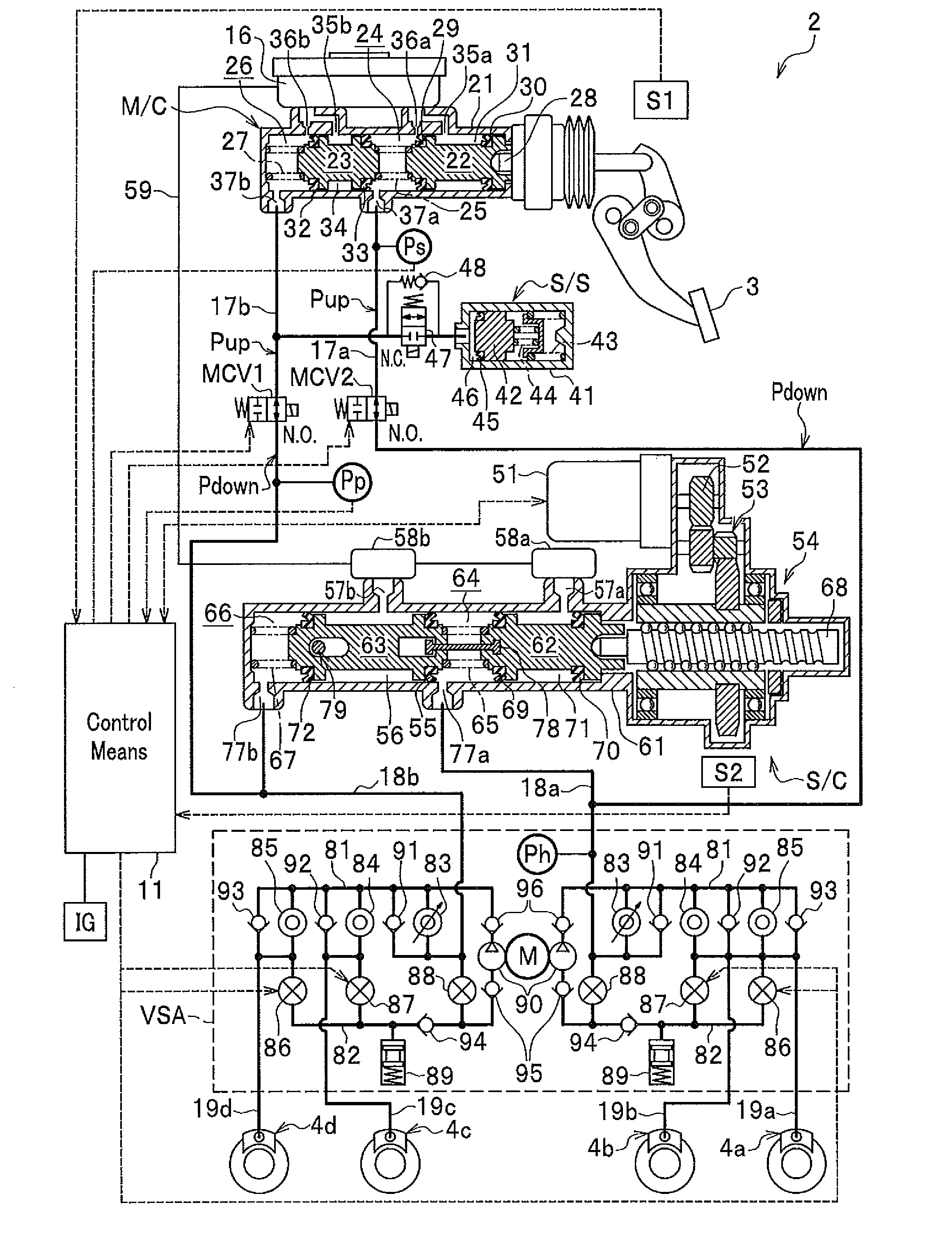
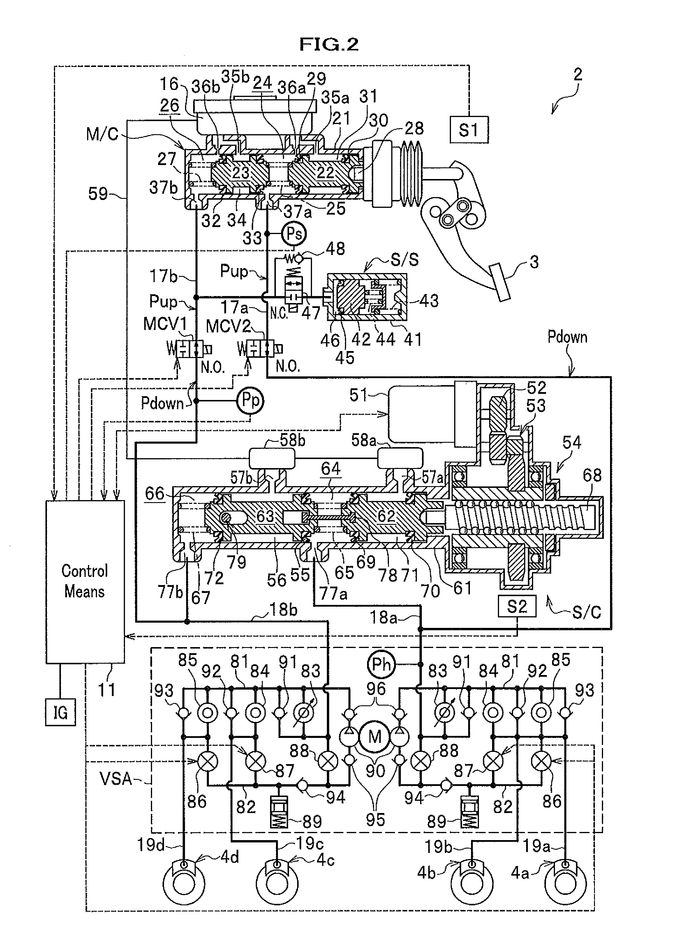
[0027]Hereinafter embodiments of the present invention are explained in detail with reference to appropriate figures.
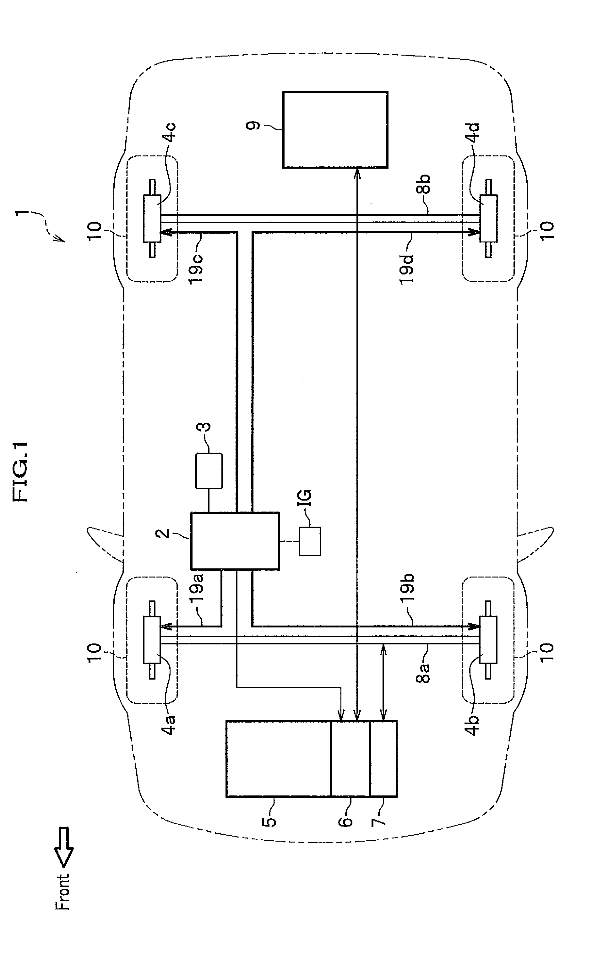
[0028]FIG. 1 is a schematic drawing of a vehicle 1 on which a vehicle brake apparatus 2 according to the present invention is installed. The vehicle 1 is equipped with four wheels 10, among which a couple of front wheels 10 are connected with an axle 8a and the other couple of rear wheels are connected with an axle 8b. A driving force generated by at least one of an engine 5 and a motor (electrical motor) 6 is transmitted through a transmission and the axle 8a to the couple of the front wheels 10 and the front wheels 10 are made to be rotating.
[0029]Additionally mechanical rotation energy of the front wheels 10 that are rotating is transmitted through the transmission 7 to the electrical motor 6, at which the mechanical rotation energy is converted to regenerated energy of electrical energy. Accordingly the front wheels 10 and the axle 8a can be braked through energy ...
PUM
 Abstract
Description
Claims
Application Information