Detection of an electrically conductive foreign object in an inductive transmission path

a technology of inductive transmission path and foreign object, which is applied in the direction of charging stations, transportation and packaging, aircraft crew accommodation, etc., can solve the problems of negative influence both on the transmission of energy and data

Inactive Publication Date: 2012-12-27
AIRBUS OPERATIONS GMBH
View PDF11 Cites 47 Cited by
  • Summary
  • Abstract
  • Description
  • Claims
  • Application Information

AI Technical Summary

Benefits of technology

[0039]In this manner, the information relating to the first parameter and the second parameter may be collected and compared in the first primary unit. This exemplary embodiment implies bidirectional data transmission or information transmission of the system. To this effect the second parameter may be conveyed from the second measuring unit to the secondary control unit, which is connected to the second modulation unit and controls the aforesaid in order to generate the second modulated alternating voltage signal. The second modulation unit may e.g. be integrated in the secondary control unit, or it may be arranged in the transmission path between the secondary control unit and the secondary

Problems solved by technology

If an electrically conductive foreign object is in the transmission path of the magnetic fields, th

Method used


Image

  • Detection of an electrically conductive foreign object in an inductive transmission path
  • Detection of an electrically conductive foreign object in an inductive transmission path
  • Detection of an electrically conductive foreign object in an inductive transmission path

Examples


Embodiment Construction

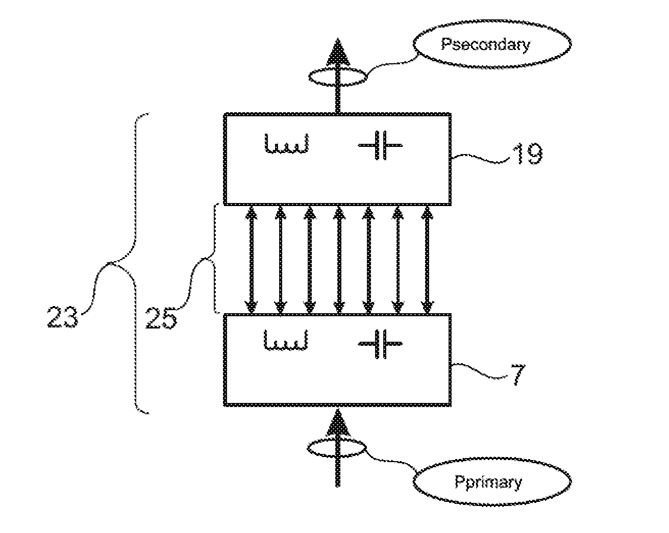
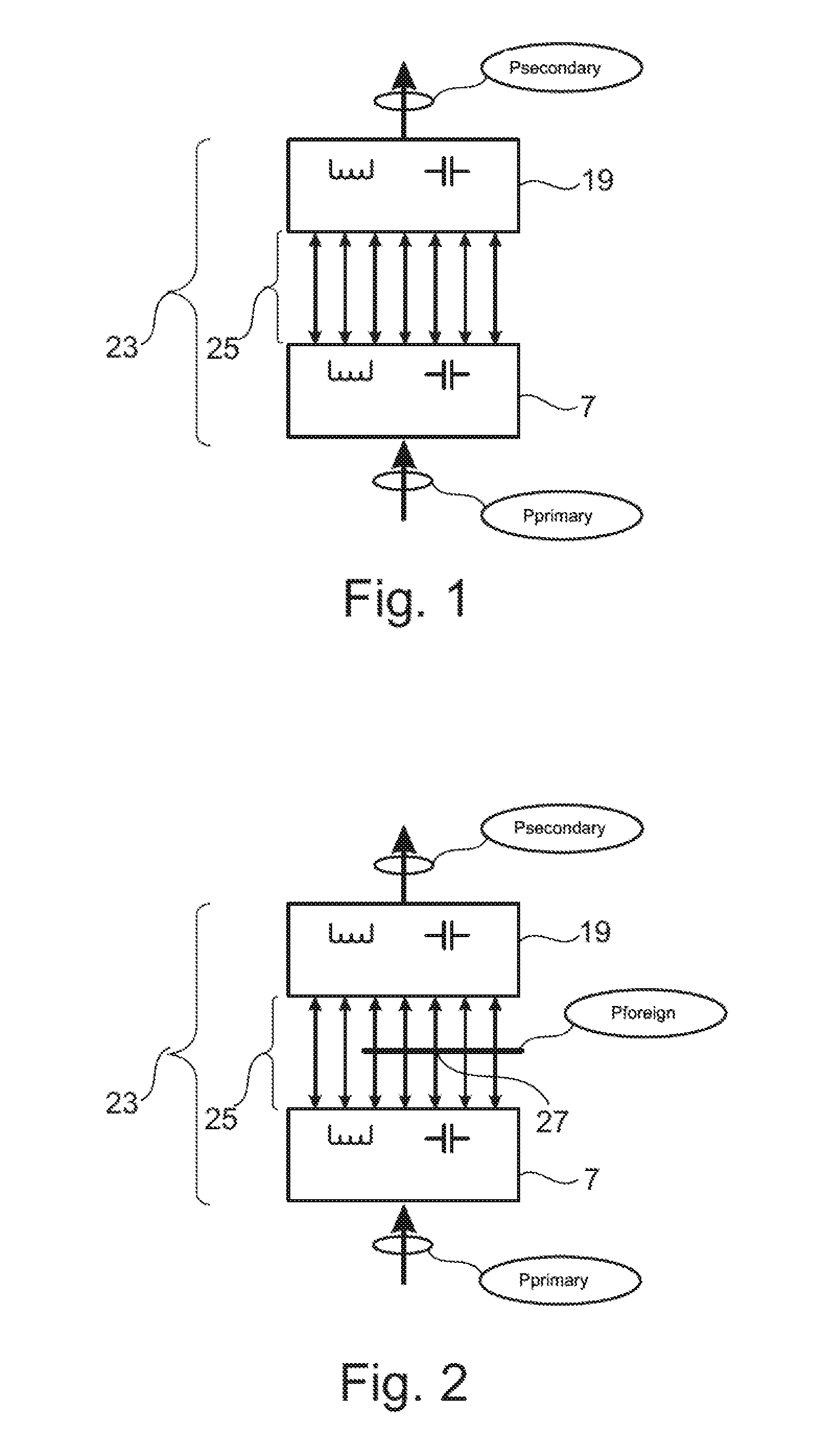
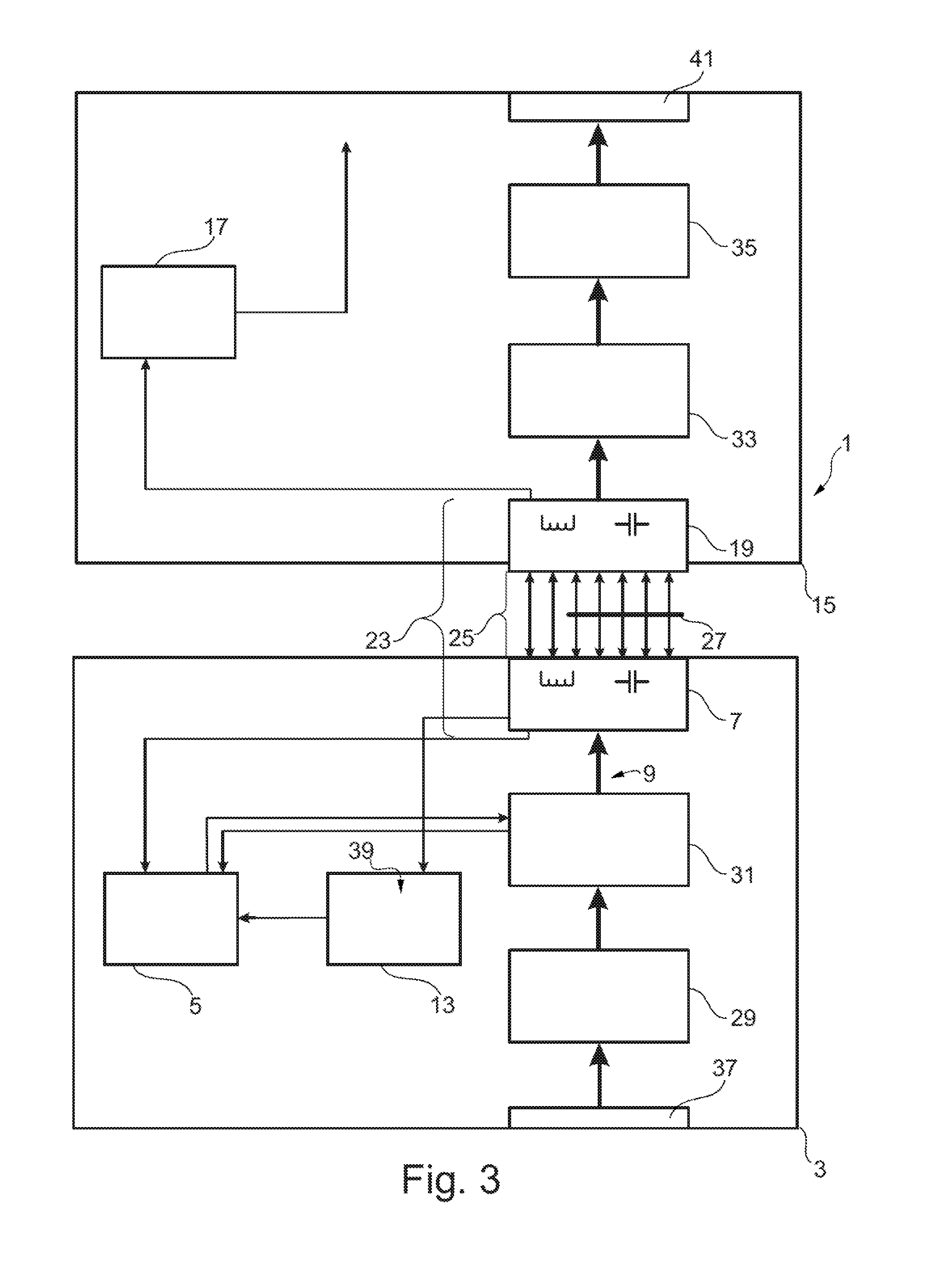
[0051]FIGS. 1 and 2 each show a section of a system 1 for contactless inductive energy transmission. Therein, FIG. 1 shows a transmission path 23 without an electrically conductive foreign object 27, and FIG. 2 with an electrically conductive foreign object 27. The inductive transmission path 23 shown in FIGS. 1 and 2 comprises an energy-supplying primary element 7 and an energy-receiving secondary element 19. The primary element 7 and the secondary element 19 in respectively comprise coils with a ferrite core. Between the primary element 7 and the secondary element 19 there is an air gap 25. The system 1 may, for example, be used in an aircraft in order to, for example, supply energy in a contactless manner to cabin installations, for example seats. The energy to be transmitted may, for example, be transmitted in a contactless manner in the form of electromagnetic radiation across the air gap 25. Therein, the magnetic efficiency may, for example, be better than 97%. In order to be ...


PUM


Abstract

A system for contactless inductive energy transmission includes a primary system and a secondary system. The primary system comprises a first modulation unit that is configured to convert an energy signal to a first modulated alternating voltage signal. Furthermore, the primary system comprises a primary element that is configured to inductively transmit the first modulated alternating voltage signal. The secondary system comprises a secondary element that is configured to receive the first modulated alternating voltage signal. Moreover, the primary system comprises a primary control unit and a first measuring unit configured to determine a first parameter of the system and to transmit it to the primary control unit. Therein, the primary control unit is configured, depending on the first parameter, to determine whether at least one electrically conductive foreign object is located in the inductive transmission path between the primary element and the secondary element.

Description

CROSS-REFERENCE TO RELATED APPLICATIONS[0001]The present application claims the benefit of the filing date of U.S. Provisional Patent Application No. 61 / 499,266 filed Jun. 21, 2011 and German Patent Application No. 10 2011 105 063.2, filed Jun. 21, 2011, the disclosures of which applications are hereby incorporated herein by reference.FIELD OF THE INVENTION[0002]The present invention relates to a system and a corresponding method for contactless inductive energy transmission that makes it possible to detect an electrically conductive foreign object in the inductive transmission path.BACKGROUND OF THE INVENTION[0003]Contactless transmission of data and energy is of importance in many technical fields. For example, electrical energy may be converted to magnetic fields which may transport the energy, for example, also through materials. In another location the magnetic fields may be converted back to electrical energy.[0004]The energy inductively transmitted in this manner may be combi...

Claims


Application Information

Patent Timeline
IPC IPC(8): H01F38/14
CPCH02J5/005B60L1/00B60L11/182Y02T90/122Y02T10/7005Y02T50/46Y02T90/14B64D11/0624Y02T10/7072B60L53/124H02J2310/44Y02T50/40Y02T10/70H02J50/60H02J50/10H02J50/12Y02T90/12
Inventor BAUER, HANS-ACHIMZYBALA, ANDRE
Owner AIRBUS OPERATIONS GMBH
Why Eureka
Try Eureka