Ceramic electronic component

Active Publication Date: 2012-12-27
MURATA MFG CO LTD
View PDF7 Cites 9 Cited by
  • Summary
  • Abstract
  • Description
  • Claims
  • Application Information

AI Technical Summary

Benefits of technology

[0015]With various preferred embodiments of the present invention, a ceramic electronic component including a metal terminal that is very difficult to detach even when a stress is externally applied is provided. In addition, the inclusion of a cut-out portion having a closed shape and extending around at least a p

Problems solved by technology

However, when eutectic solder is used, if the ceramic electronic component is used under a high-temperature environment, a problem arises in that the eutectic solder is fused and the metal terminal is detached from the main body of the electronic component.
), a problem arises in that the lead-free high-temperature gradually softens and the bond strength between the metal terminal and the main body of the electronic component significantly de

Method used


Image

  • Ceramic electronic component
  • Ceramic electronic component
  • Ceramic electronic component

Examples


Embodiment Construction

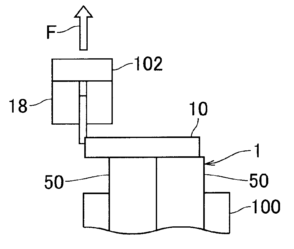
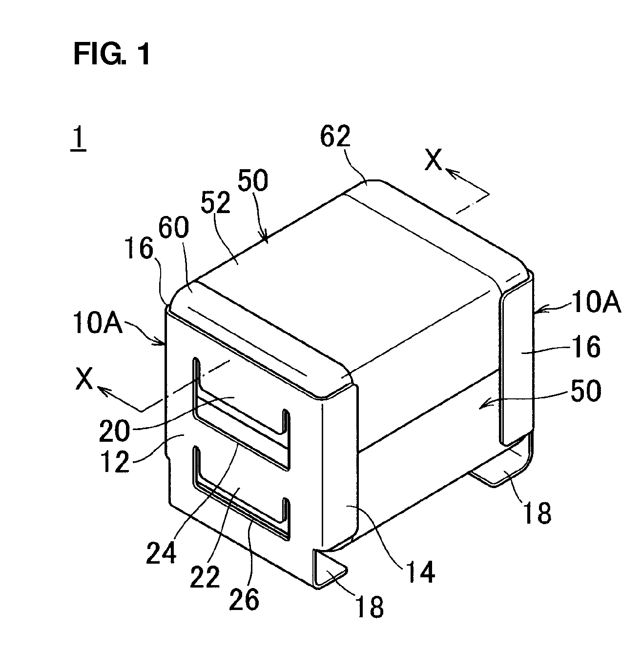
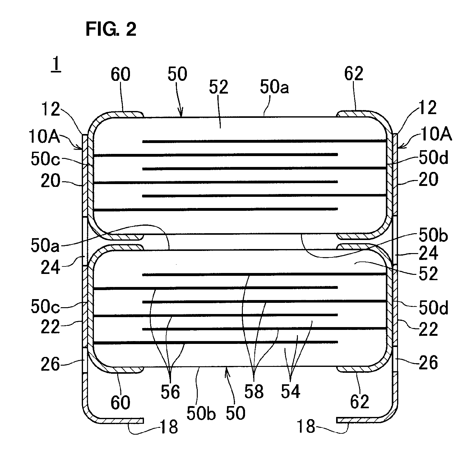
[0031]FIG. 1 is an external perspective view that illustrates a ceramic electronic component according to a preferred embodiment of the present invention. FIG. 2 is a cross-sectional view taken along X-X in FIG. 1. A ceramic electronic component 1 includes two metal terminals 10A used as one set and a stack of two electronic-component main bodies 50 sandwiched between the metal terminals 10A.

[0032]Each of the electronic-component main bodies 50 includes two opposed major surfaces 50a and 50b, two opposed end surfaces 50c and 50d, and two opposed side surfaces. The electronic-component main body 50 includes a stack 52 preferably having a substantially rectangular parallelepiped shape and external electrodes 60 and 62 disposed on both ends (end surfaces 50c and 50d), respectively. The stack 52 includes a plurality of ceramic layers 54 and internal electrodes 56 and 58 disposed between the ceramic layers 54. The corners and ridges of the stack 52 include rounded portions R.

[0033]The in...


PUM

PropertyMeasurementUnit
Shapeaaaaaaaaaa
Widthaaaaaaaaaa
Areaaaaaaaaaaa

Abstract

A ceramic electronic component includes two electronic-component main bodies and two metal terminals. Each of the metal terminals includes a base, ribs on left and right sides of the base, and a mounting portion below the base. The base includes two bonding portions to be bonded to respective external electrodes of the two electronic-component main bodies and cut-out portions each having a closed shape and being disposed below the respective bonding portions. The ribs are bent from the left and right sides of the base in the width direction toward the electronic-component main body. The ribs extend from the top of the base in the height direction to the vicinity of the mounting-side major surface of the mounting-side electronic-component main body and do not reach the mounting portion. The mounting portion is bent from the bottom of the base toward the electronic-component main body.

Description

BACKGROUND OF THE INVENTION[0001]1. Field of the Invention[0002]The present invention relates to a ceramic electronic component, such as a ceramic capacitor.[0003]2. Description of the Related Art[0004]Typically, in a ceramic electronic component with a metal terminal, an external electrode on the surface of the main body of the electronic component and the metal terminal are bonded to each other with eutectic solder or lead-free solder. However, when eutectic solder is used, if the ceramic electronic component is used under a high-temperature environment, a problem arises in that the eutectic solder is fused and the metal terminal is detached from the main body of the electronic component. When lead-free high-temperature solder (with a melting point of approximately 245° C.) is used, the bond strength between the metal terminal and the main body of the electronic component at ordinary temperatures is high. However, if the ceramic electronic component is used under a high-temperatur...

Claims


Application Information

Patent Timeline
IPC IPC(8): H01L41/047H01F5/00H01G4/12H01C7/13
CPCH01G4/30H01G4/232H01G2/06H01G4/38
Inventor ITAGAKI, YOJIKOTANI, JUN
Owner MURATA MFG CO LTD
Why Eureka
Try Eureka