Alternator for vehicle with heat dissipating fin

a technology of heat dissipator and vehicle, which is applied in the field of alternative devices, can solve the problems of the reduction in and achieve the effects of facilitating the control of the sub-fin, and reducing the production cost of the rectifier

Active Publication Date: 2012-12-27
DENSO CORP
View PDF2 Cites 4 Cited by
  • Summary
  • Abstract
  • Description
  • Claims
  • Application Information

AI Technical Summary

Benefits of technology

[0016]The depth of the recesses and the height of the protrusions are both less than the thickness of the heat dissipator. This facilitates the ease with which the sub-fins are made by pressing the second surface of the heat dissipator to form the recesses and the protrusions simultaneously and permits the mechanical strength of the heat dissipator to be controlled by regulating the amount of material of the heat dissipator which is to be left between each of the recesses and a corresponding one of the protrusions.
[0017]The width of the recesses is greater than that of the protrusions. This permits a plate to be deformed to make the sub-fins easily without stamping or punching out the plate.
[0018]The heat dissipator may be designed to include a main fin and an auxiliary fin. The main fin has the rectifying devices mounted thereon and an outer circumference extending around the rotor. The auxiliary fin is disposed on the outer circumference of the main fin and has the sub-fins formed thereon. The auxiliary fins work to create smooth flows of the cooling air from outside an outer periphery of the rectifier into the main fin, thereby enhancing the dissipation of heat from the rectifying devices installed on the main fin.
[0019]The heat dissipator has a slant shoulder formed between the main fin and the auxiliary fin. This facilitates the flow of cooling air from a high altitude (i.e., an upstream side) to a low altitude (i.e., a downstream side), thereby enhancing the introduction of the cooling air from the auxiliary fin to the main fin. The shoulder also functions to increase the mechanical strength of the heat dissipator, thereby decreasing the stress acting on the rectifying devices installed on the main fin.
[0020]The main fin may have through holes formed between the rectifying devices and the auxiliary fin. This directs flows of the cooling air moving along the sub-fins of the auxiliary fin behind the main fin. This results in an increase in heat dissipating area of the heat dissipator, thus enhancing the efficiency in cooling near the rectifying devices.
[0021]Each of the through hole lies between adjacent two of the sub-fins in a direction of rotation of the rotor. This ensures the stability of entry of the cooling air into the through holes with a small resistance without disturbing flows of the cooling air along the sub-fins, which leads to an increase in volume of the cooling air passing through the holes.

Problems solved by technology

The press forming of the sub-fins results in no burr between adjacent two of the sub-fins, thereby eliminating the need of an additional process of finishing the sub-fins, which leads to a decrease in production cost of the rectifier.

Method used


Image

  • Alternator for vehicle with heat dissipating fin
  • Alternator for vehicle with heat dissipating fin
  • Alternator for vehicle with heat dissipating fin

Examples


Embodiment Construction

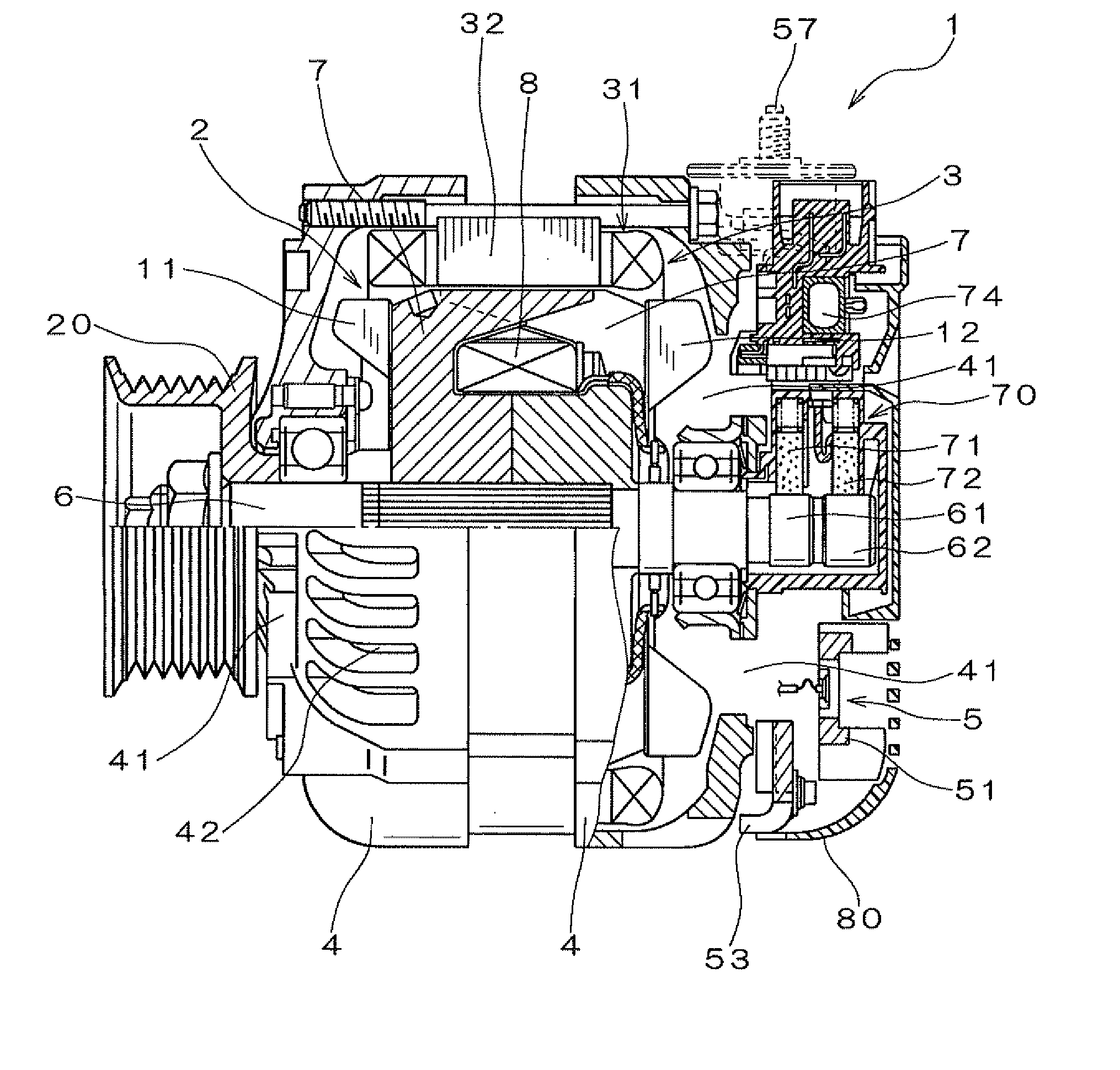
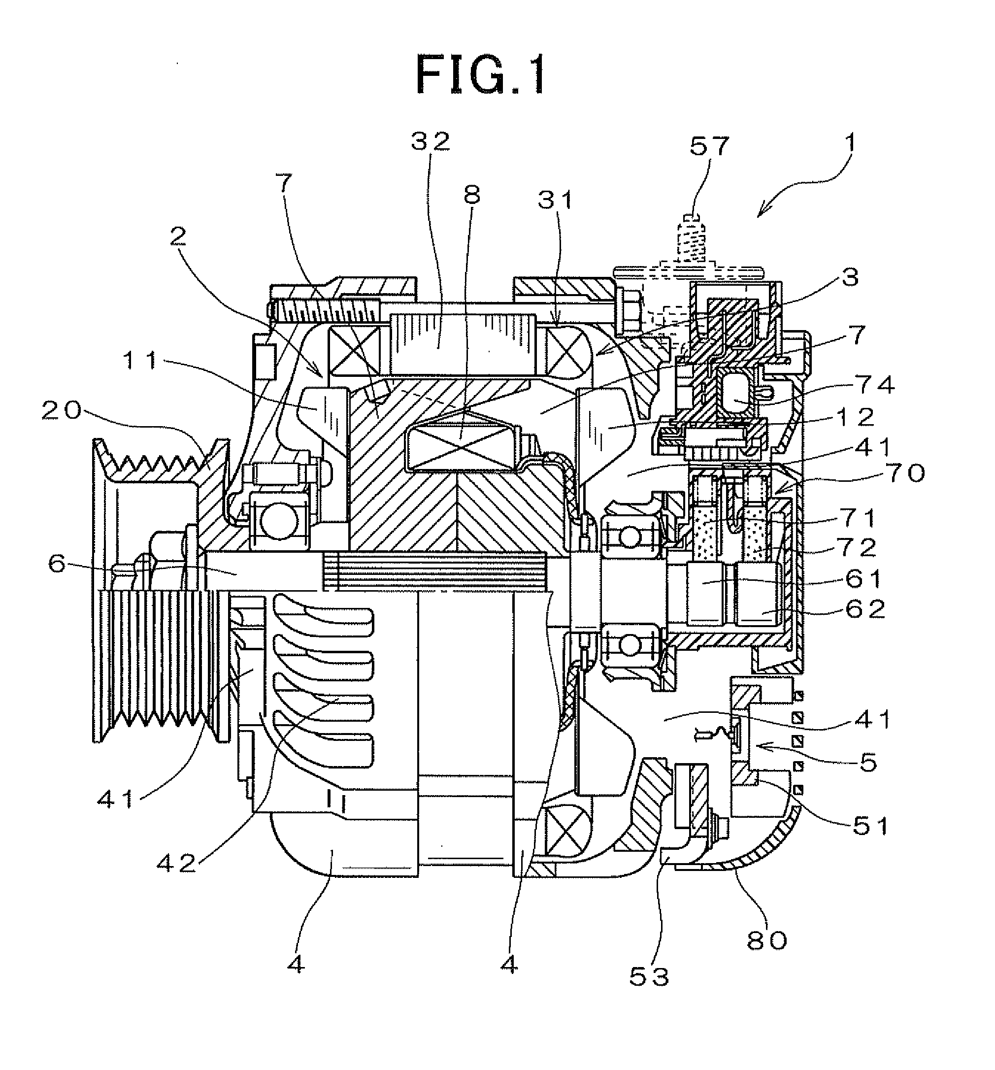
[0040]Referring to the drawings, wherein like reference numbers refer to like parts in several views, particularly to FIG. 1, there is shown an AC generator or alternator 1 for automotive vehicles according to the first embodiment.

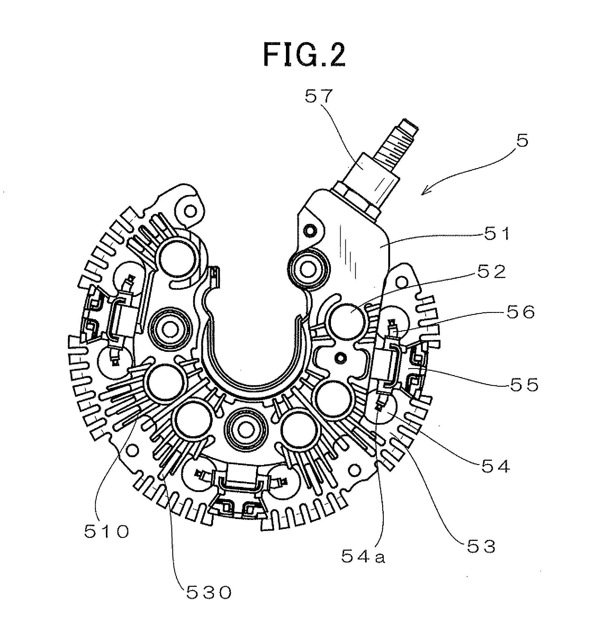
[0041]The alternator 1 consists essentially of a rotor 2, a stator 3, a frame assembly 4, and a rectifier 5.

[0042]The rotor 2 is, as clearly shown in FIG. 1, made up of a pair of pole cores 7 with claws and a field coil 8 retained between the pole cores 7. The field coil 8 is made of copper wire which is coated with an insulator and wound coaxially in the form of a cylindrical shape. A rotating shaft 6 is inserted through the pole cores 7. A cooling fan 11 is welded to an end wall of a front one (i.e., a left one, as viewed in FIG. 1) of the pole cores 7. The cooling fan 11 works to suck air from the front of the alternator 1 and discharge it axially and radially of the alternator 1. Similarly, a centrifugal fan 12 is welded to an end wall of a rear one of...


PUM


Abstract

An alternator for a vehicle is provided which is equipped with a heat dissipator and a cooling air generator. The heat dissipator is disposed in a rectifier to cool rectifying devices. The cooling air generator generates a flow of cooling air to the heat dissipator. The heat dissipator has a plurality of sub-fins formed thereon. Each of the sub-fins is defined by a combination of a protrusion and a recess. The protrusions are formed on one of opposed major surfaces of the heat dissipator, while the recesses are formed on the other major surface, one in coincidence with each of the protrusions in a thickness-wise direction of the heat dissipator. This permits the heat dissipator to be pressed to form the protrusions and the recesses to make the sub-fins simultaneously, thus allowing a heat-dissipating area to be increased to ensure a desired degree of heat capacity thereof.

Description

CROSS REFERENCE TO RELATED DOCUMENT[0001]The present application claims the benefit of Japanese Patent Application Nos. 2011-138999 and 2012-20877 filed on Jun. 23, 2011 and Feb. 2, 2012, disclosures of which are incorporated herein by reference.BACKGROUND OF THE INVENTION[0002]1. Technical Field of the Invention[0003]The present invention relates generally to an alternator which may be installed in passenger automobiles or trucks, and more particularly to such an alternator having installed therein a heat dissipator which is equipped with heat dissipating fins.[0004]2. Background Art[0005]Typical automotive alternators are equipped with a rectifier which has a positive-side fin radiator and a negative-side fin radiator to cool rectifying devices installed on the positive-side and negative-side fin radiators. Japanese Patent Publication No. 3775235 teaches such fin radiators with circular or elongated holes which are formed by a press to increase heat dissipating area of the fin rad...

Claims


Application Information

Patent Timeline
Patent Type & Authority Applications(United States)
IPC IPC(8): H02K9/06
CPCH02K9/06H02K11/05
Inventor KONAYA, KAZUYOSHIHAMADA, HIROSHIMASHINO, MIKIOKONDOH, SEIJI
Owner DENSO CORP
Why Eureka
Try Eureka