Switching power supply with quick transient response

a technology of switching power supply and transient response, which is applied in the direction of electric variable regulation, process and machine control, instruments, etc., can solve the problems of increasing circuit complexity and chip area, and achieve the effect of improving the transient response capability of switching power supply, reducing output voltage and increasing output voltag

Active Publication Date: 2012-12-27
SOUTHEAST UNIV
View PDF3 Cites 26 Cited by
  • Summary
  • Abstract
  • Description
  • Claims
  • Application Information

AI Technical Summary

Benefits of technology

[0009]The present invention improves the transient response capability of switching power supply by adding an additional delay controller on the existing PWM controller of the switching power supply. When the load current of the switching power supply changes abruptly and the output voltage fluctuates and goes beyond the delay voltage range, the delay controller will take the place of the PWM controller and functions.
[0010]If the output voltage is too high, the delay controller will switch off the P-MOS tube (P type power MOS tube) and switch on the N-MOS tube (N type MOS tube), so that the output filter capacitor discharges and thereby the output voltage is decreased. After the delay control loop operates for one or two PWM oscillation cycles, the switching power supply will automatically switch to be controlled by the PWM controller, while the delay controller still detects whether the output voltage is within the delay voltage range; if the output voltage goes beyond the delay voltage range again, the switching power supply will switch to be controlled by the delay controller again, till the output voltage is stabilized.
[0011]If the output voltage is too low, the delay controller will switch on the P-MOS tube and switch off the N-MOS tube, so that the output filter capacitor is charged, and thereby the output voltage is increased. After the delay controller operates for one or two PWM oscillation cycles, the switching power supply will automatically switch to be controlled by the PWM controller, while the delay controller still detects whether the output voltage is within the delay voltage range; if the output voltage goes beyond the delay voltage range again, the switching power supply will switch to be controlled by the delay controller again, till the output voltage is stabilized.
[0012]The new added delay controller only operates when the output voltage fluctuation amplitude goes beyond the delay voltage range, and therefore has no influence on other features of the switching power supply. In addition, the output voltage of the switching power supply provided in the present invention is variable, and the transient response rate against load current fluctuations can be effectively improved at different output voltage.

Problems solved by technology

For a switching power supply unit with variable output voltage, additional circuits are required to produce limit which changes by following the output voltage, as a result of which, the circuit complexity and chip area are increased.

Method used


Image

  • Switching power supply with quick transient response
  • Switching power supply with quick transient response
  • Switching power supply with quick transient response

Examples


Embodiment Construction

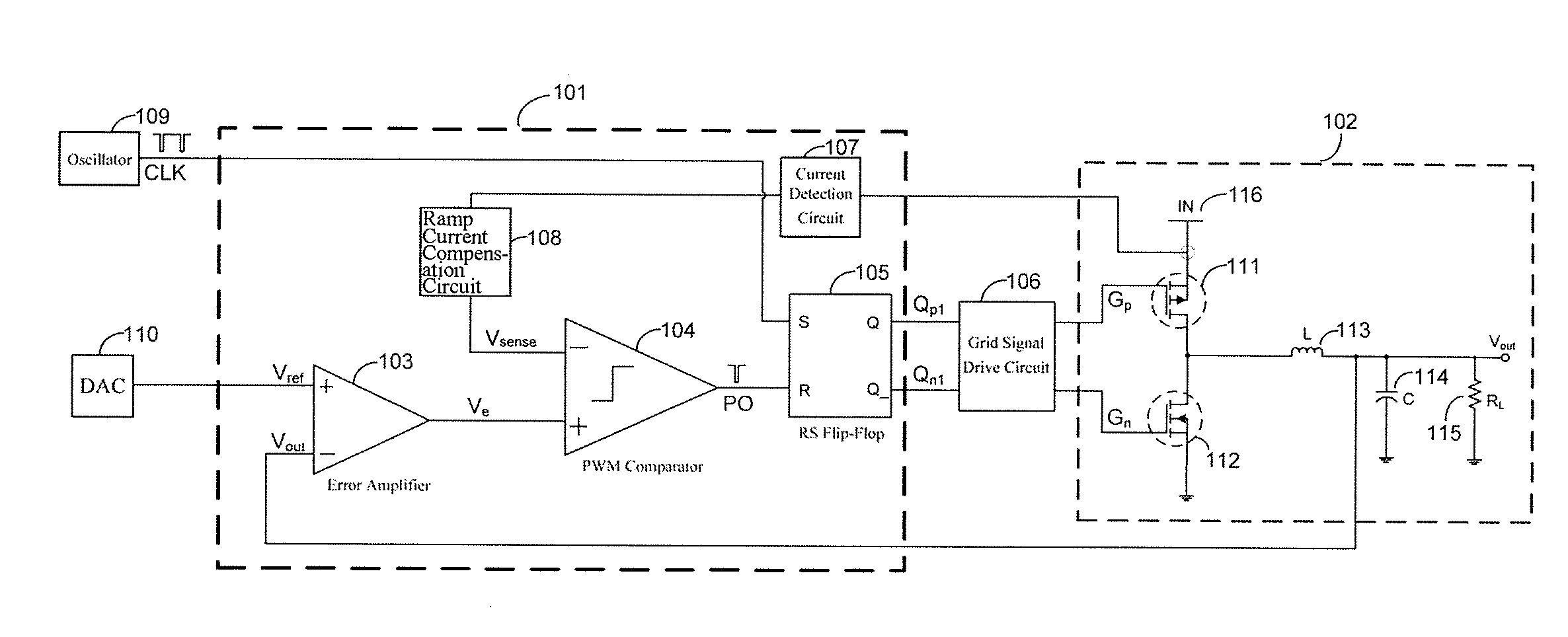
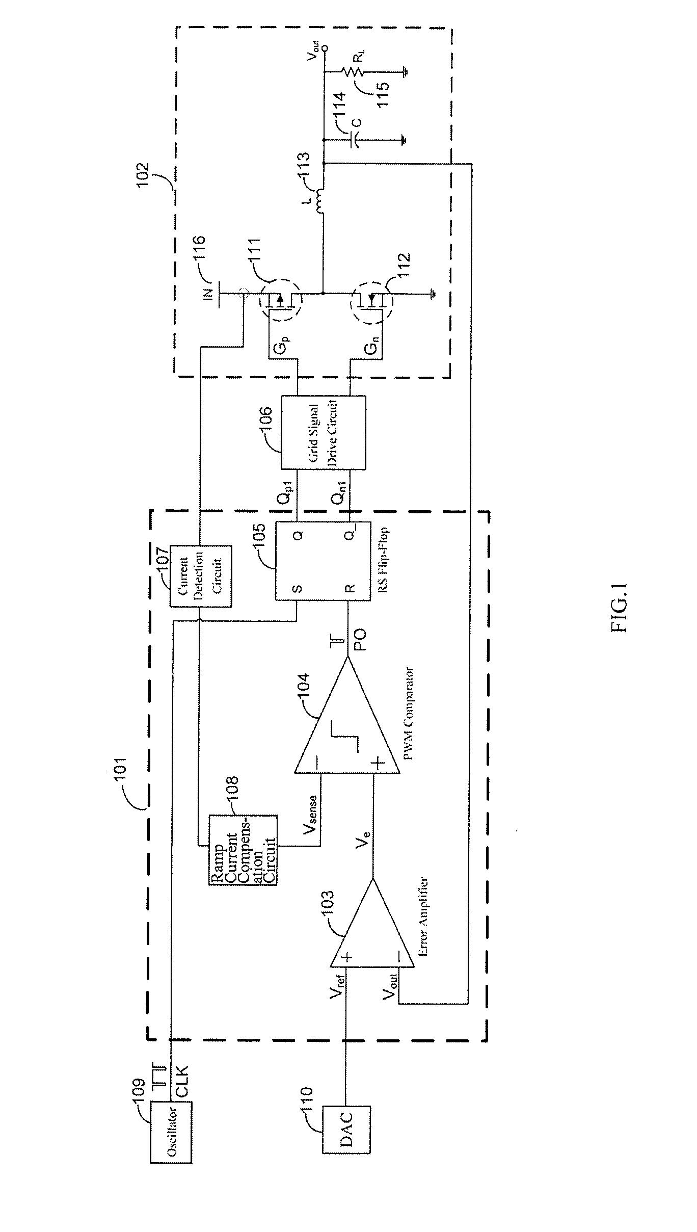
[0026]A switching power supply with quick transient response, comprising: a power stage 102 with an inductor 113, a PWM controller 101, and a grid signal drive circuit 106, wherein, a D / A converter 110 designed to produce a reference voltage is connected to a reference voltage input terminal of the PWM controller 101, an oscillator 109 designed to produce clock signals is connected to a clock signal input terminal of the PWM controller 101, the output terminal of the power stage 102 is connected to a voltage feedback signal input terminal of the PWM controller 101 which utilizes the output voltage from the switching power supply as the feedback signal, the PWM controller 101 is designed to collect the current signal of the inductor 113 in the power stage 102 and take the collected current signal as the input signal for the current feedback signal input terminal of the PWM controller 101, an output terminal of the grid signal drive circuit 106 is connected to an input terminal of the...


PUM


Abstract

A switching power supply with a quick transient response is provided. A hysteretic control loop which comprises a hysteretic controller (117) and a control signal gate (116) is added to the original PWM control loop of the switching power supply. The hysteretic controller (117) is used to detect an output voltage (Vout) of the switching power supply and compare the output voltage (Vout) of the switching power supply with a reference voltage (Vref). When a load current (Iout) of the switching power supply is suddenly changed, the output voltage (Vout) of the switching power supply fluctuates. If the output voltage (Vout) of the switching power supply is in a setting range of the hysteretic voltage, output terminals (SELp, SELn) of the hysteretic controller (117) are in a low potential, and the control signal gate (116) selects output signals (Qp1, Qn1) from a PWM controller (101) as input signals of a gate signal drive circuit (106). If the fluctuation of the output voltage (Vout) of the switching power supply exceeds the setting range of the hysteretic voltage, an output terminal (SELp, SELn) of the hysteretic controller (117) outputs a high potential, and the control signal gate (116) selects output signals (Qp2, Qn2) of the hysteretic controller (117) as input signals of the gate signal drive circuit (106), so the operation of switching tubes (111, 112) at the power lever (102) of the switching power supply is controlled to stabilize the output voltage (Vout).

Description

BACKGROUND[0001]1. Field[0002]The present invention relates to a switching power supply with quick transient response against abrupt changes of load current, in particular to a switching power supply with variable output voltage and quick transient response, which is helpful for improving transient response rate of switching power supply, reducing fluctuation amplitude of output voltage, and reducing the time required for stabilizing the output voltage.[0003]2. Description of the Related Art[0004]Nowadays, as microprocessors and DSPs (Digital Signal Processors) develop, there is a demand for switching power supply with high current variation rate and quick transient response. In fact, microprocessors and DSPs are rapid-changing loads for switching power supply. For instance, to reduce power consumption, in idle state, microprocessors and DSPs enter into “Sleep Mode”, in which the working current is very low; once needed, microprocessors and DSPs create instantaneous high current; th...

Claims


Application Information

Patent Timeline
Patent Type & Authority Applications(United States)
IPC IPC(8): G05F1/618
CPCH02M3/1588H02M2003/1566Y02B70/1466H02M2001/0025Y02B70/10H02M1/0025H02M3/1566
Inventor SUN, WEIFENGYANG, MIAOJIN, YOUSHANLIU, SICHAOXU, SHENLU, SHENGLISHI, LONGXING
Owner SOUTHEAST UNIV
Why Eureka
Try Eureka