

Compound test method of high voltage direct current transmission converter valve
a converter valve and high-voltage technology, applied in power supply testing, instruments, air-break switches, etc., can solve the problems of insufficient equivalence and difficulty in assembling a full-laden test circuit to real operation conditions, and achieve the effect of wide application, good test effect, and large choice room
- Summary
- Abstract
- Description
- Claims
- Application Information
AI Technical Summary
Benefits of technology
Problems solved by technology
Method used
Image

Examples
example 1
[0028]In the high voltage direct current converter compound test, this invention method working principle is described as below under the double injection mode:
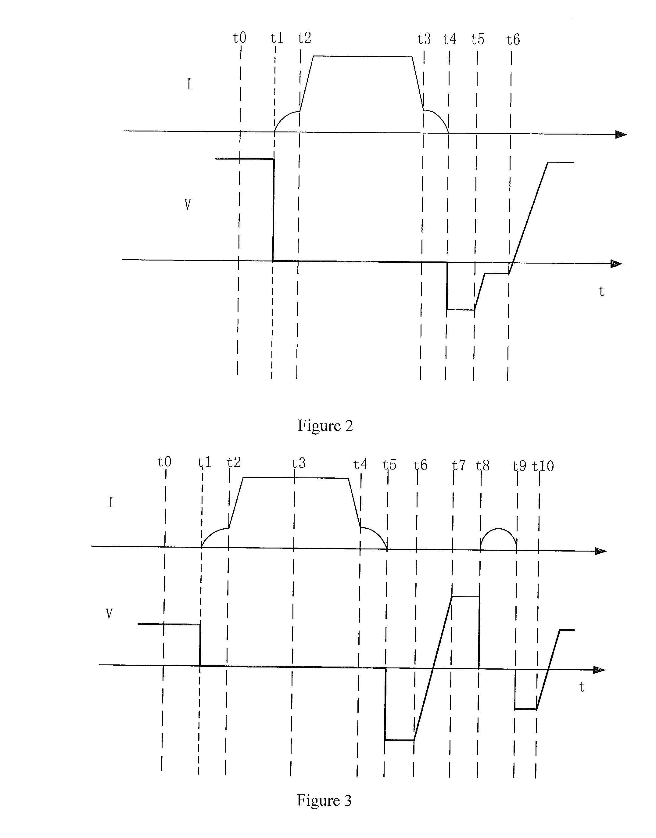
[0029]FIG. 2 is the voltage and current periodical waveform graph (20 ms) of the test valve under double injection mode in the compound test.
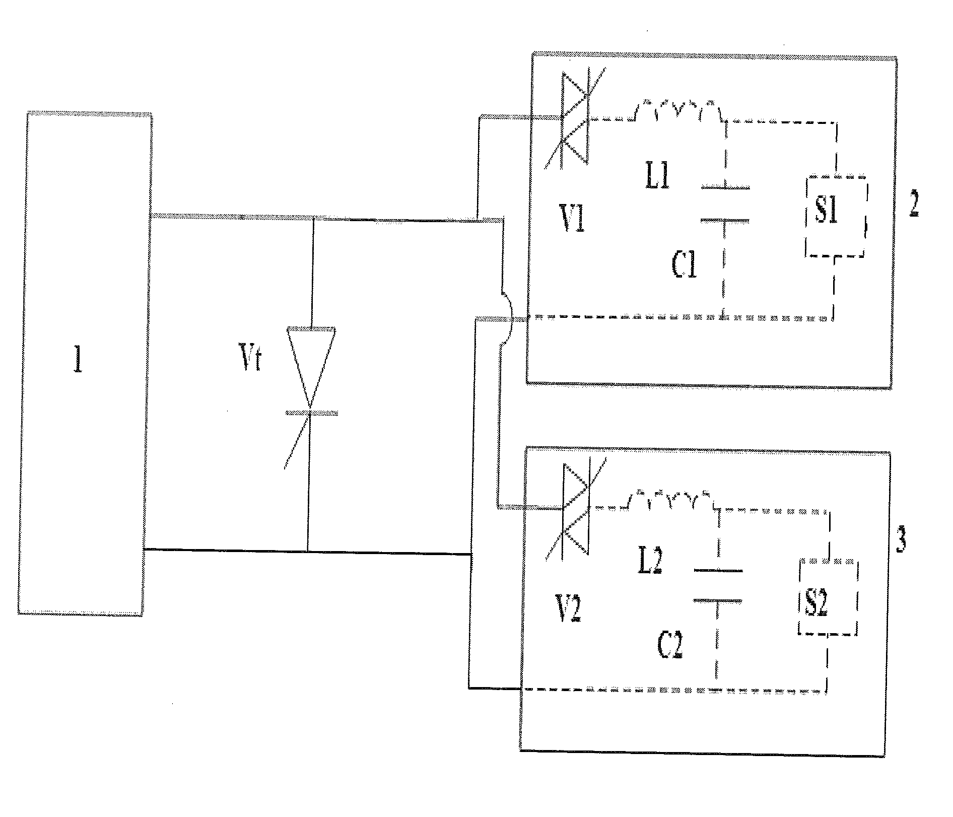
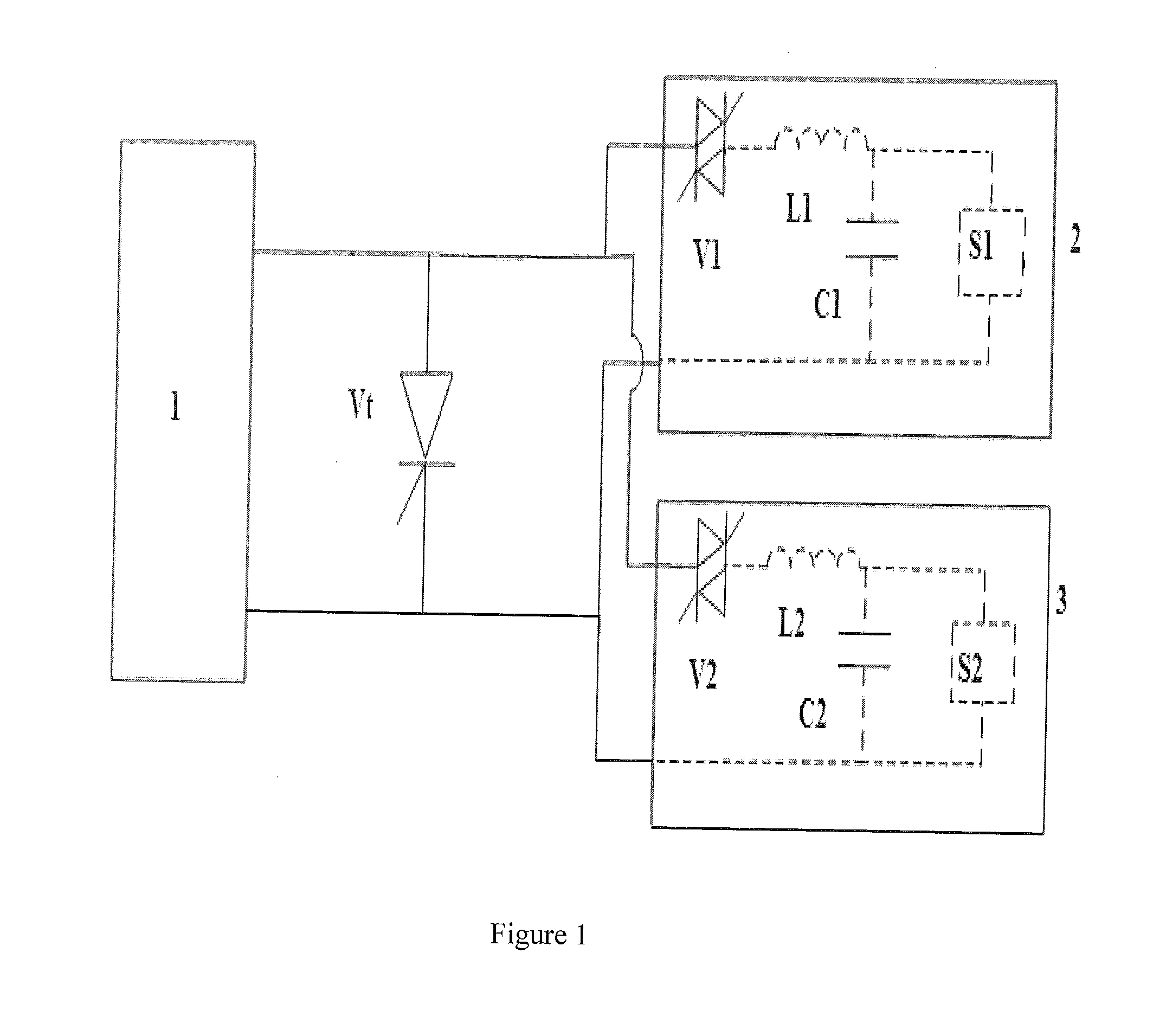
[0030]At t0, the test valve affords forward high voltage from high voltage source 2;
[0031]At t1, turn on the test valve Vt and auxiliary valve V1, and the resonant current from the high voltage source 2 passes through the test valve Vt;
[0032]At t2, bring the current from the large direct current source 1 into test vavle Vt, and it affords the direct current in conducting interval;
[0033]At t3, turn on the auxiliary V2 before direct current off, and the resonant current from the high voltage source 3 passes through test valve Vt;
[0034]At t4, the resonant current from the high voltage source 3 is off, trigger auxiliary valve V2, and the test valve Vt afford reserve high voltage from the hig...
example 2
[0037]In the high voltage direct current converter compound test, this invention method working principle is described as below under the triplicate injection mode:
[0038]FIG. 3 is the voltage and current periodical waveform graph (20 ms) of the test valve under triplicate injection mode in the compound test.
[0039]At t0, the test valve affords forward high voltage from high voltage source 2;
[0040]At t1, turn on the test valve Vt and auxiliary valve V1, and the resonant current from the high voltage source 2 passes through the test valve Vt;
[0041]At t2, bring the current from the large direct current source 1 into test vavle Vt, and it affords the direct current in conducting interval;
[0042]At t3, charge device S1 charges resonant capacitor C1 of the high voltage source 2, to recovery its voltage to t0 level;
[0043]At t4, turn on the auxiliary V2 before the direct current off, the resonant current from high voltage source 3 passes through the test valve;
[0044]At t5, the resonant curren...
PUM
 Abstract
Description
Claims
Application Information