Magnetic recording system used thermal-assisted-magnetic- recording head

a recording head and magnetic recording technology, applied in the field of magnetic recording systems, can solve the problems of reduced performance of the magnetic recording apparatus, reduced total optical propagation efficiency, and increased power consumption of the whole magnetic recording apparatus, so as to reduce the spot size can be reduced, and the spot size of the light can be reduced

Inactive Publication Date: 2012-12-27
HITACHI LTD
View PDF2 Cites 21 Cited by
  • Summary
  • Abstract
  • Description
  • Claims
  • Application Information

AI Technical Summary

Benefits of technology

[0023]The tapered portion in the optical waveguide core made of a high-refractive-index material has a function to reduce the spot size of the light. The spot size can be reduced as the light propagates in the tapered portion. For this reason, the light of the spot size in the nanometer order can be emitted from the bottom surface of the magnetic head. Moreover, the wavefront of the light coupled to the tapered portion is made flat in the rectangular portion. For this reason, the spot size of the light can be reduced in the tapered portion with high total optical propagation efficiency.
[0024]Moreover, in order to further improve the total optical propagation efficiency of the spot size converter, the distance between the multi-mode-thin-film-like core and the optical waveguide core made of a high-refractive-index material may be in the range of a half of a half width of the spot size in the thickness direction of the light that propagates along the multi-mode-thin-film-like core ±40%. If the distance is thus adjusted, while highly efficient light coupling of the light of a large spot size emitted from the optical source provided on the upper surface of the magnetic head and the multi-mode-thin-film-like core is maintained, the light that propagates through the multi-mode-thin-film-like core can be coupled to the optical waveguide

Problems solved by technology

For this reason, in the case where the light directly enters the core having the width and the thickness in the submicron order, total optical propagation efficiency is low due to a large coupling loss of the light undesirably.
This requires increase in the output light power of the optical source for implementing the thermally assisted magnetic recording, and results in increase in the power consumption in the whole magnetic recording apparatus and increase in the temperature within the apparatus.
Particularly, increase in the temperature leads to reduction in performance of

Method used


Image

  • Magnetic recording system used thermal-assisted-magnetic- recording head
  • Magnetic recording system used thermal-assisted-magnetic- recording head
  • Magnetic recording system used thermal-assisted-magnetic- recording head

Examples


Embodiment Construction

[0054]Hereinafter, with reference to the drawings, embodiments according to the present invention will be described.

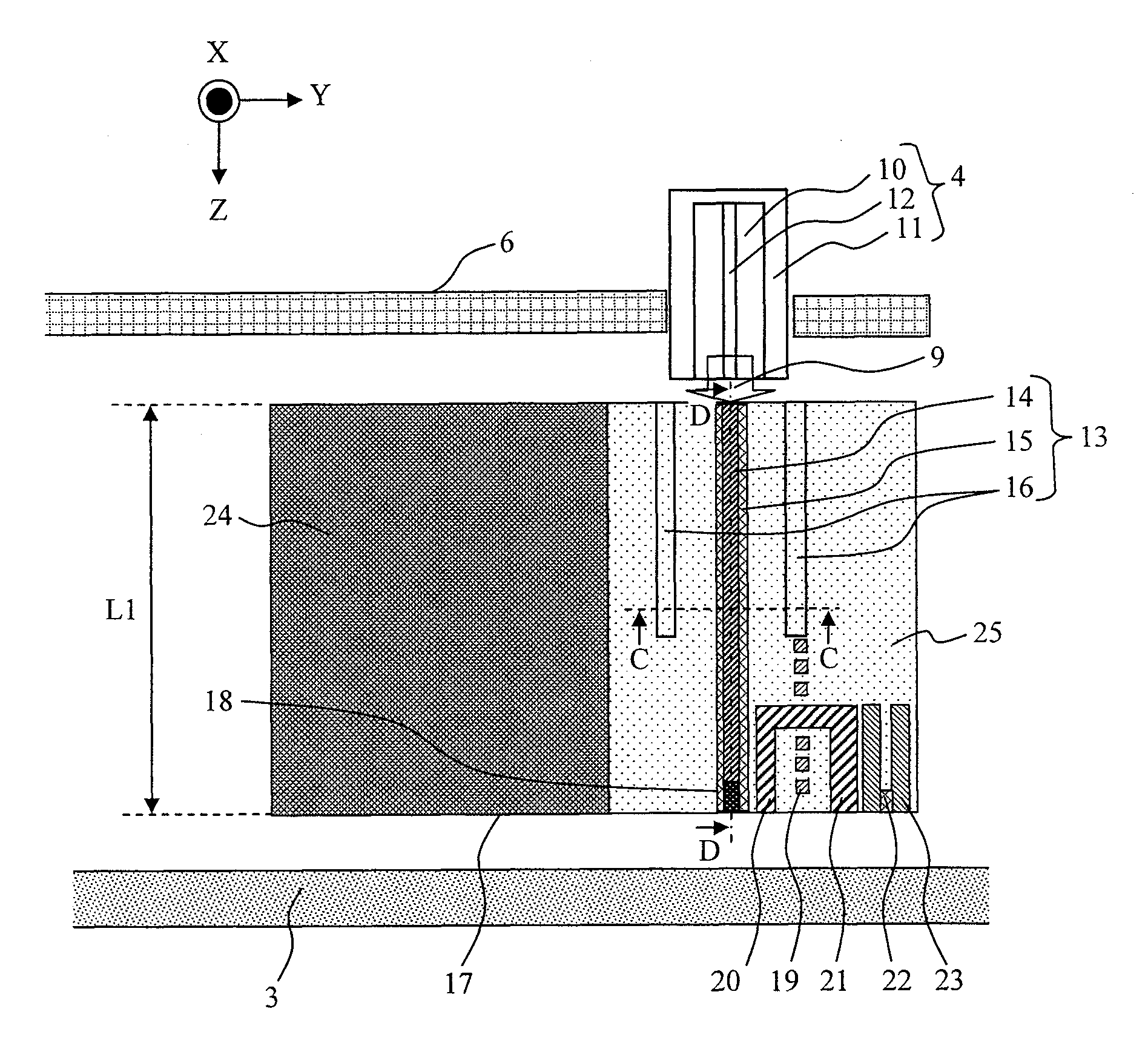
[0055]Using FIG. 4, FIG. 5, and FIG. 1, an embodiment of information recording apparatus according to the present invention having a high efficient light integration mechanism will be described. FIG. 4 is a schematic view showing an essential part of a magnetic recording apparatus according to the embodiment in which a cover of a casing 1 is removed. FIG. 5 is a cross-sectional schematic view taken along A-A in FIG. 4. FIG. 1 is a schematic view of a cross section of a magnetic head around the spot size converter according to the present invention, and is an enlarged view of a region of B1-B2-B3-B4 in FIG. 5.

[0056]As shown in FIG. 4, a magnetic recording medium 3 is fixed to a spindle 2 rotated and driven by a motor, and rotated. A magnetic head 5 is fixed to a suspension 6, and moved by a voice coil motor 7 to be positioned at a desired track in the magnetic recording...


PUM


Abstract

A thermally assisted recording magnetic head is provided in which a magnetic recording medium can be irradiated with light having a spot size reduced in the submicron order with high total optical propagation efficiency. In a magnetic head, a spot size converter that propagates the light from an optical source in the magnetic head is provided adjacent to a main pole. The spot size converter includes a cover layer having a refractive index lower than that of a clad material and formed in contact with the optical waveguide core, and is formed in a shape composed of a substantially rectangular shape in a light traveling direction and a tapered shape where the width is increased toward the bottom surface of the magnetic head. The optical waveguide core having the cover layer formed is vertically interposed between multi-mode-thin-film-like cores that can excite a first or higher-order optical waveguide mode.

Description

CLAIM OF PRIORITY[0001]The present application claims priority from Japanese patent application JP 2011-139424 filed on Jun. 23, 2011, the content of which is hereby incorporated by reference into this application.BACKGROUND OF THE INVENTION[0002]1. Field of the Invention[0003]The present invention relates to a thermally assisted recording magnetic head and a magnetic recording apparatus including the same.[0004]2. Description of the Related Art[0005]The information recording density of magnetic recording apparatuses has been increasing steadily, and the size of a magnetic recording mark per bit has been becoming smaller and smaller. So far, the recording bit size in the magnetic recording apparatus has been mainly reduced by reducing the size of a recording magnetic head and magnetic particles used for a magnetic recording medium. However, since the magnetic recording density exceeded 1 Tbit / inch2, there has been a concern that the magnetic information recorded on the magnetic reco...

Claims


Application Information

Patent Timeline
IPC IPC(8): G11B11/00
CPCG11B5/314G02B6/1228G11B2005/0021G11B5/6088
Inventor IWANABE, YASUHIKOMIYAMOTO, HARUKAZU
Owner HITACHI LTD
Why Eureka
Try Eureka