
Device for providing radiofrequency signal connections

Inactive Publication Date: 2012-12-27
AIRBUS OPERATIONS GMBH
View PDF4 Cites 5 Cited by
  • Summary
  • Abstract
  • Description
  • Claims
  • Application Information

AI Technical Summary

Benefits of technology

[0006]An idea of the present invention is therefore to provide a method and a device for providing radiofrequency signal connections for users in which the transmitted radiofrequency signals can be emitted and received by means of a common transmitting and receiving antenna without limiting their performance and without having a negative effect on one another.
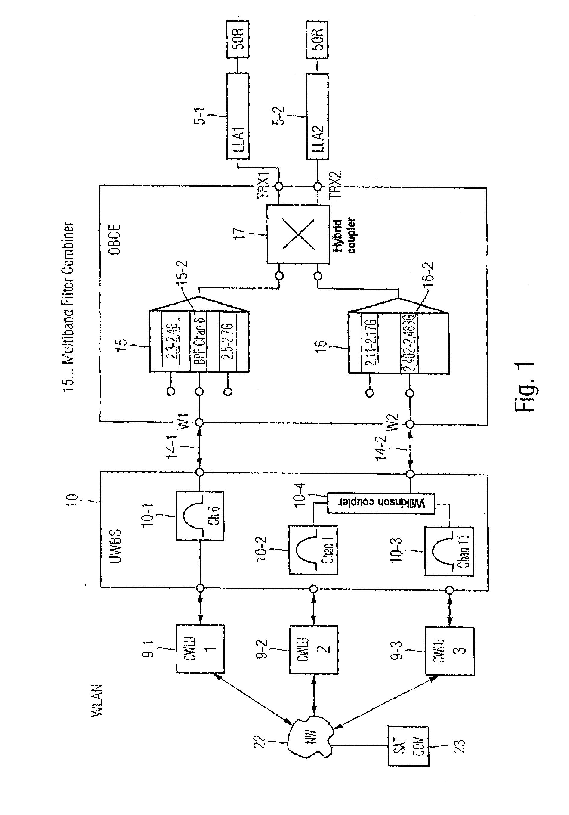
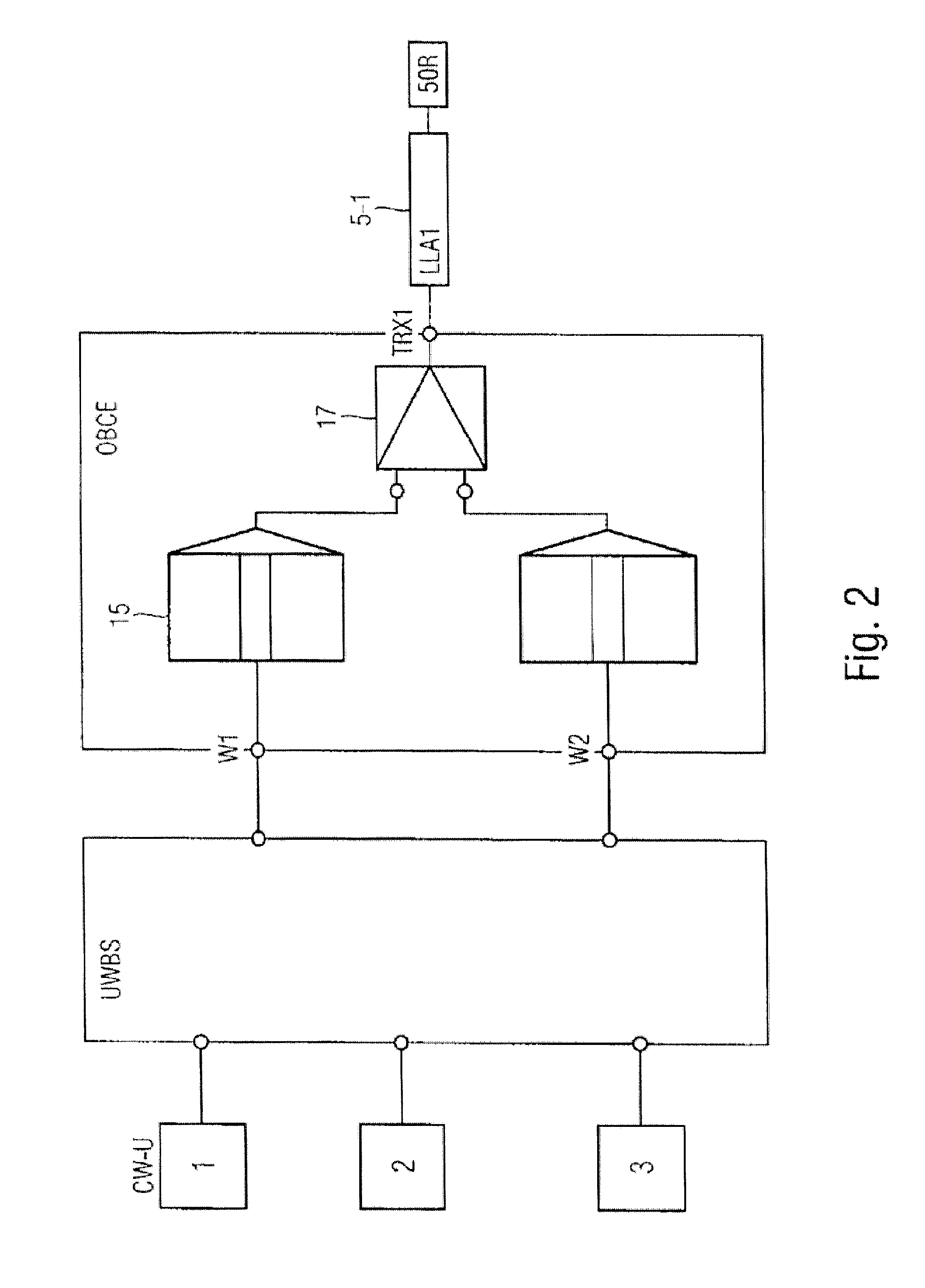
[0008]Therefore, one advantage of the device according to the invention is that as a result of the use of two different filters, namely a channel filter and a band pass filter which is connected thereto, a required filter gradient for each of the two filters for achieving a predetermined stop band attenuation can be relatively low, and thus the circuitry complexity when implementing filters of this type is relatively low. Moreover, the channel filters and the band pass filters, which only have to have a relatively low filter gradient in each case, are of a small installation size and can thus be accommodated in an available installation space, for example in an aeroplane. Moreover, filters of this type are of a relatively low weight, in such a way that fuel can be saved as a result if they are installed in an aeroplane, for example.
[0032]In one embodiment of the device according to the invention, a filter means consisting of a channel filter and a band pass filter has a stop band attenuation of more than 50 dB, preferably of more than 70 dB. This stop band attenuation makes it possible to operate all of the access points simultaneously at a maximum data transfer rate of up to 54 Mbit / s.

Problems solved by technology

Since the available frequency spectrum is limited, radiofrequency bands for different services are increasingly being arranged packed tightly together, and in many cases no distinct guard bands or protective frequency bands are provided between the various radiofrequency bands.

Method used


Image

  • Device for providing radiofrequency signal connections
  • Device for providing radiofrequency signal connections
  • Device for providing radiofrequency signal connections

Examples


Embodiment Construction

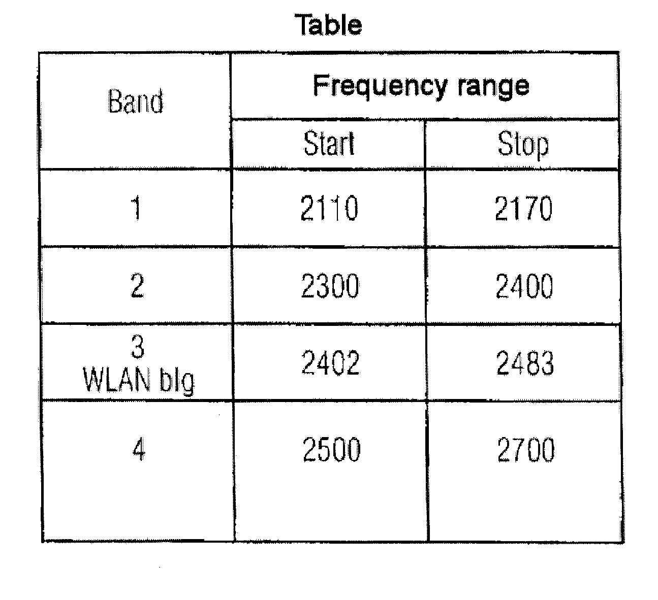
[0048]As can be seen from the block diagram in FIG. 1, the device 1 according to the invention is provided for supplying radiofrequency signal connections in a vehicle 2, in particular in an aircraft, for example a passenger aeroplane. The aeroplane 2 comprises a passenger cabin 3, in which aeroplane passengers and crew members may be located. The passengers and crew members have mobile terminals, such as mobile telephones, smartphones, laptops, PDAs and the like. In the example shown in FIG. 1, three mobile terminals 4-1, 4-2 and 4-3 are shown in the passenger cabin 3. At least one transmitting and receiving antenna 5-i is further provided in the passenger cabin 3. In the embodiment shown in FIG. 1, two transmitting and receiving antennas 5-1, 5-2 are provided in the passenger cabin 3. These transmitting and receiving antennas 5-1, 5-2 are laid in the passenger cabin 3. The transmitting and receiving antenna 5-i may for example be what is known as a leaky line antenna. The mobile t...


PUM


Abstract

What is disclosed is a device for providing radiofrequency signal connections for users, wherein the device comprises a plurality of access points which transmit or receive radiofrequency signals in different predetermined radiofrequency bands and are each connected via a transmission and reception signal path to at least one shared transmitting and receiving antenna, filter means being provided in the transmission and reception signal paths respectively and isolating the radiofrequency bands sufficiently from one another and from predetermined mobile radio frequency bands.

Description

CROSS-REFERENCE TO RELATED APPLICATIONS[0001]This application is a continuation of and claims priority to PCT / EP2011 / 050467, filed Jan. 14, 2011, which claims the benefit of and priority to U.S. Provisional Application No. 61 / 294,985, filed Jan. 14, 2010, and German Patent Application No. 10 2010 000 909, filed Jan. 14, 2010, the entire disclosures of which are incorporated herein by reference.FIELD OF THE INVENTION[0002]The invention relates to a device for providing radiofrequency signal connections, in particular WLAN connections, for users located in a passenger cabin of an aircraft.BACKGROUND OF THE INVENTION[0003]In aircraft, in particular aeroplanes, wireless radio-linked transmission systems are increasingly being used, and provide communication within the aeroplane during flight or when the aeroplane is located on the ground. The communication partners are passengers or crew members, who are located for example in the passenger cabin of the aeroplane. During the flight, the...

Claims


Application Information

Patent Timeline
IPC IPC(8): H04W84/12
CPCB64D11/0015Y02T50/46H04B1/52H04B1/0057Y02T50/40
Inventor SCHIRRMACHER, MARTINFROHN, ANDREAS
Owner AIRBUS OPERATIONS GMBH
Learn More