
Two-layered preform obtained by injection overmolding

a two-layer, preform technology, applied in mechanical equipment, transportation and packaging, other domestic objects, etc., can solve the problems of affecting the quality of the preform, so as to reduce ensure the perfect alignment of the core. , the effect of reducing the capacity of the inner layer

Inactive Publication Date: 2012-12-27
MOLMASA APLICACIONES TECNICAS
View PDF5 Cites 12 Cited by
  • Summary
  • Abstract
  • Description
  • Claims
  • Application Information

AI Technical Summary

Benefits of technology

"The patent describes a mold and method for manufacturing two-layered preforms by plastic injection overmolding. The mold includes a primary molding cavity and an overmolding cavity connected to separate hot channels. A supporting member is used to hold the core in position during the molding operation of the first layer, and the openings in the first layer are filled and covered with the overmolding material of the second layer. The technical effect of this mold and method is that it ensures a uniform thickness of the first layer and prevents elastic deformation of the core during the molding operation of the first layer, which is important for the manufacturing of two-layered preforms."

Problems solved by technology

A common problem in the molds of any type of apparatus for manufacturing two-layered preforms by injection overmolding is that the cores, due to their slenderness and to their long cantilevered portion, can be slightly deformed elastically inside the primary molding cavities during the injection of the primary molding material of the first layer due to the differences in the temperature, and therefore in the fluidity, of the plastic material injected in an initial phase and in a final phase of the injection process, and to the random distribution of this material with different degrees of fluidity inside the empty space defined between the primary molding cavity and the core.
Given that the thicknesses of the layers of the two-layered preform are subject to strict dimensional tolerances, a slight deformation of the core during the injection operation of the first layer results in variations in the thickness of both layers in opposite sides of the two-layered preform which may be unacceptable, taking into account that the thickness of the layers is reduced to significantly small values during the subsequent blow molding process to form the bottle or another container from the two-layered preform.
However, this arrangement has several drawbacks.
On one hand, the incorporation of the injection valve arranged in the closed bottom of the cavity involves a relatively complex construction and operation, and on the other hand, the fact that the core is no longer supported during the final phase of the molding operation does not ensure a perfect alignment of the core in the molding cavity during the entire injection process of the preform.
These supports leave holes in the preform.
A drawback of this arrangement is that the incorporation of the cylinder and piston assembly at the end of the blow molding cavity is complex and expensive.
Furthermore, if, as usual, the preforms are to be allowed to cool in order to remove them from the core and store them for a subsequent distribution and use in a plurality of blow molding apparatuses, this would limit the use of such preforms with holes to only those blow molding apparatuses which are equipped with the mentioned cylinder and piston assembly to extrude the protrusion and close the holes before the blow molding operation.
However, there is not described nor suggested that the two-layered plastic product obtained by such process is useful to be subsequently blow molded, and in fact the alternate arrangement of monolayer regions of different materials in the hollow plastic product is a serious drawback since the joining areas therebetween are substantially parallel to the pressure direction during a blow molding operation and this involves a risk of said joining areas to be broken.
A drawback related with the sequential co-injection process in comparison with the overmolding process I that the former is not suitable for injecting only two layers forcing to inject an odd number thereof, in general three or five.
It neither permits to accurately control the extent of the intermediate layer or layers nor the uniformity in the width of the layers.
A lack of precision in the preform can result in irregularities in a container obtained by blow molding the preform, and such irregularities will be the more accentuated the more thinner are the layers of the preform.

Method used


Image

  • Two-layered preform obtained by injection overmolding
  • Two-layered preform obtained by injection overmolding
  • Two-layered preform obtained by injection overmolding

Examples


first embodiment

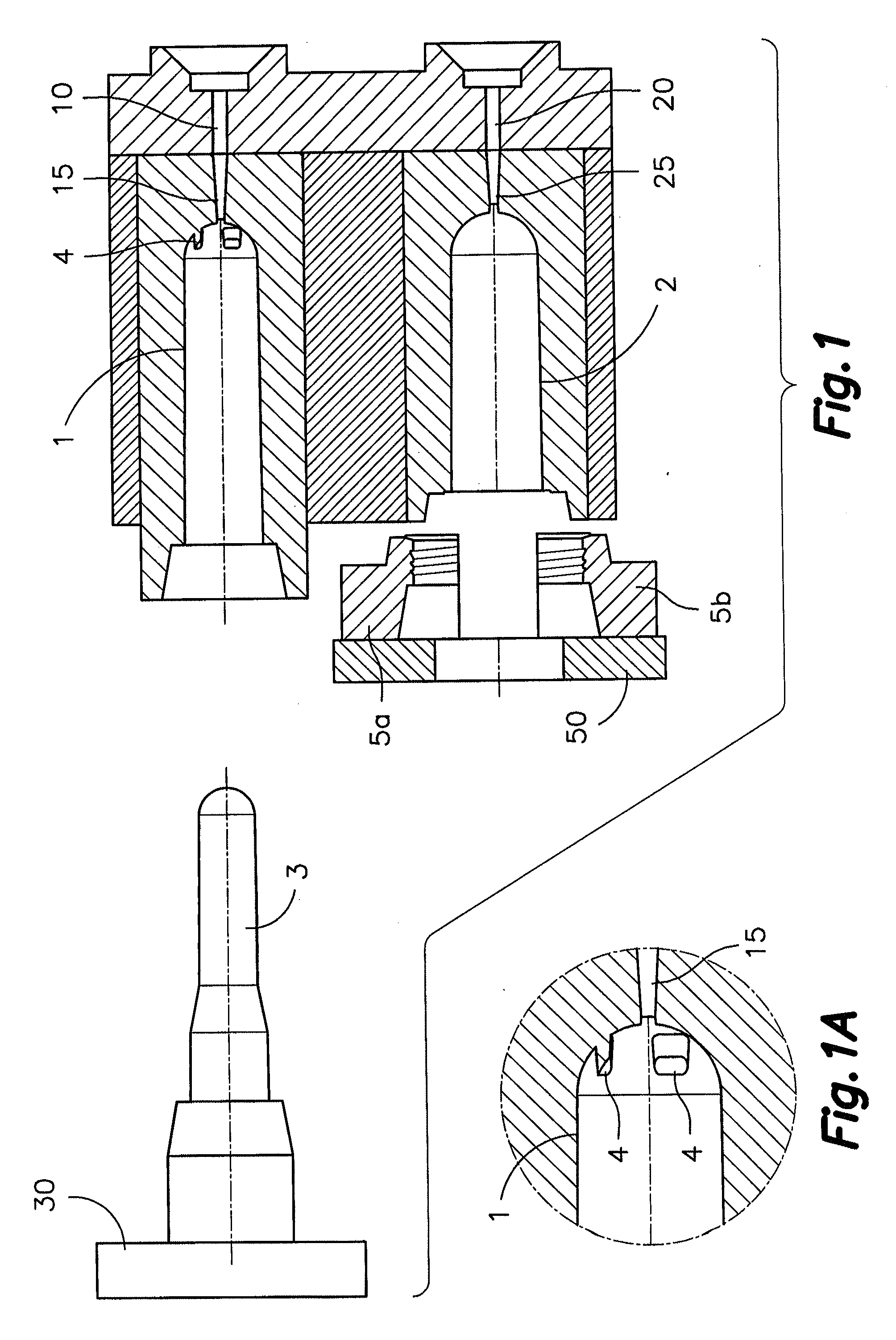
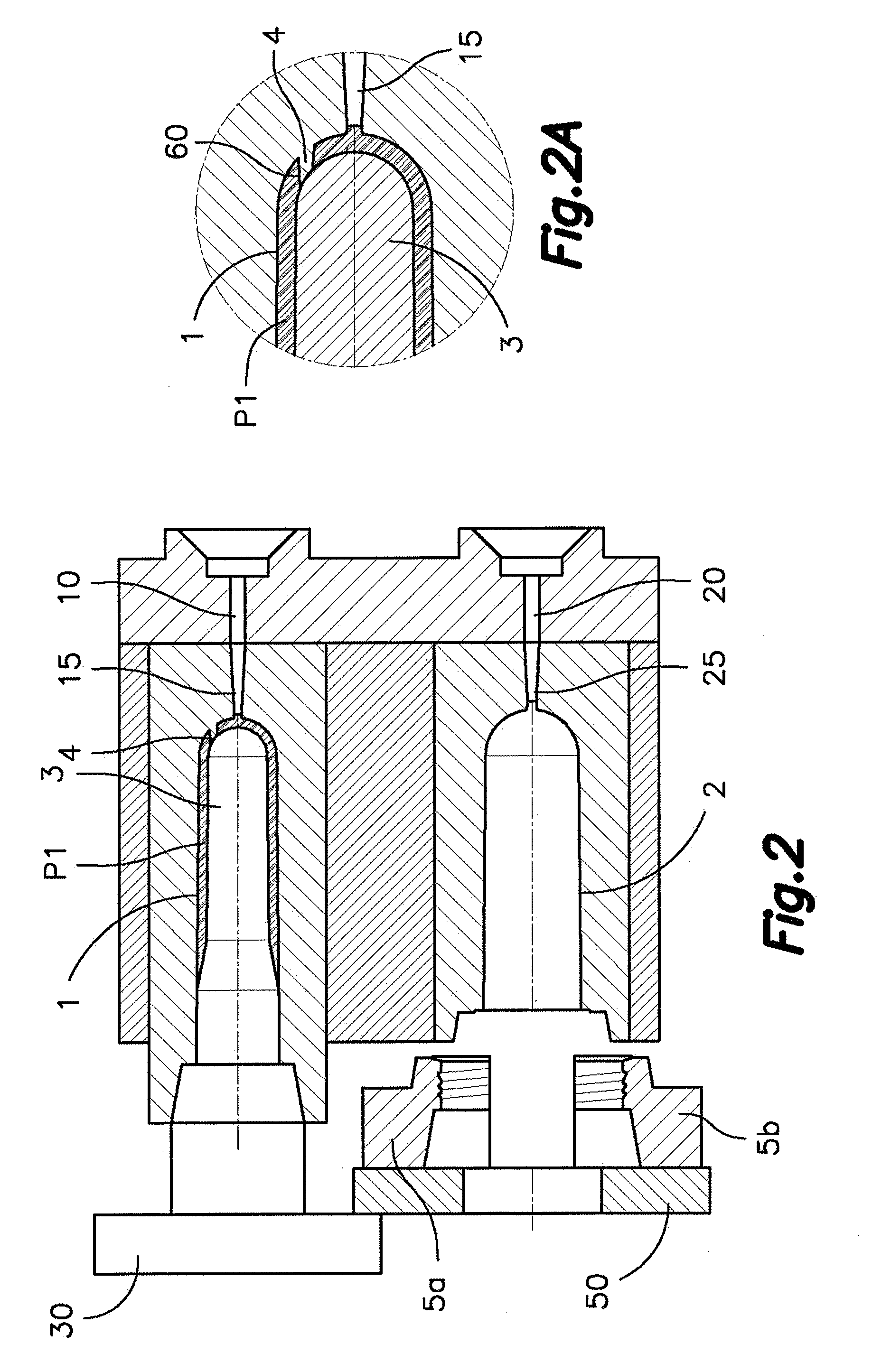
[0049]Referring first to FIG. 1, there are shown the different parts forming a mold for manufacturing two-layered preforms by injection overmolding according to a mold and / or a method. The mold comprises a primary molding cavity 1, which is connected to a first hot channel 10 for supplying a primary molding material into said primary molding cavity 1 through a first injection nozzle 15, and an overmolding cavity 2 connected to a second hot channel 20 for supplying an overmolding material into said overmolding cavity 2 through a second injection nozzle 25. In the embodiment shown, the primary molding cavity 1 and overmolding cavity 2 are stationary, although this is not essential. The mold further comprises a core 3 connected to a mobile plate 30 of an injection molding apparatus (not shown) operated to alternately introduce said core 3 into the primary molding cavity 1 and into the overmolding cavity 2. In the embodiment shown in FIG. 1, the mold is completed with a pair of neck hal...

second embodiment

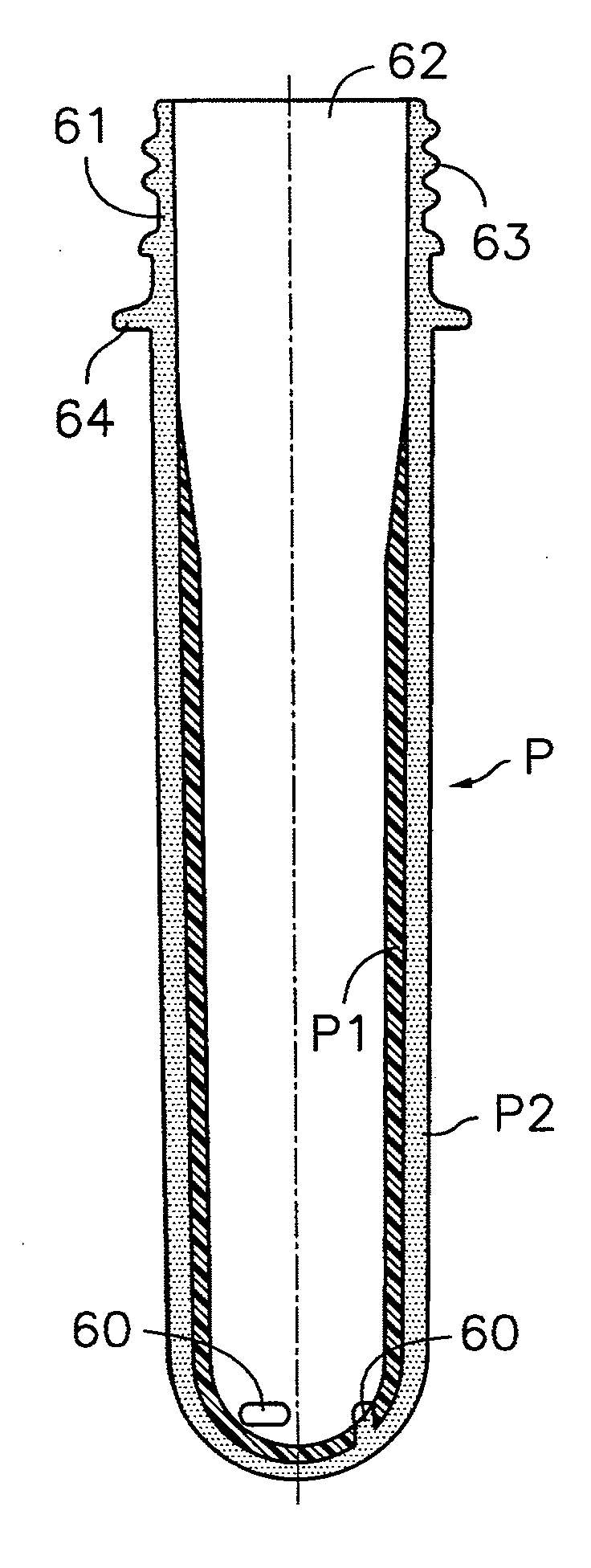
[0070]FIG. 14 shows another example of two-layered preform P which can be produced by means of the mold and / or the method. The two-layered preform P of FIG. 14 is a preform with a very thin wall, for example of less than 2.1 mm. The first layer P1 provides a single layer for most of the wall of the preform, optionally including a neck (not shown) at the open end. This first layer P1 has a thickness equal to or less than 2.1 mm. The second layer P2 is very small and only covers the region corresponding to the closed bottom of the first layer P1, with the bulges 65 of the second layer P2 covering but not filling the openings 60 left by the supporting members 4. It must be indicated that it is not necessary for the second layer P2 to cover all the closed bottom of the preform with a thickness substantially equivalent to the thickness of the first layer P1. The overmolding cavity 2 can alternatively be configured to form the second layer P2 with a much smaller thickness and / or with a sm...


PUM

PropertyMeasurementUnit
thicknessaaaaaaaaaa
thicknessaaaaaaaaaa
moldingaaaaaaaaaa

Abstract

The two-layered preform includes a tubular body having a mouth providing a neck at a first end thereof and a closed bottom at an opposite second end. At least part of the tubular body is formed by a first layer (P1) made of a primary molding material and a second layer (P2) made of an overmolding material. The first layer (P1) is an inner layer made of a primary molding material providing a barrier effect against light by absorption, and the second layer (P2) is an outer layer made of an overmolding material providing a barrier effect against light by reflection. The neck is formed with the overmolding material of the second layer (P2) not coated by the primary molding material of the first layer (P2).

Description

CROSS-REFERENCE TO RELATED APPLICATIONS[0001]This application is a Divisional Application of U.S. patent application Ser. No. 12 / 575,711, filed Oct. 8, 2009 which is a Continuation-in-Part (CIP) Application of PCT International Application No. PCT / ES2008 / 000226, filed Apr. 11, 2008, which claims benefit of priority from PCT International Application No. PCT / ES2007 / 000202, filed Apr. 11, 2007. The contents of these applications are incorporated herein by reference.TECHNICAL FIELD[0002]The present invention relates to a two-layered preform obtained by injection overmolding and provided with an inner layer made of a material capable of providing a barrier effect against light by absorption and an outer layer made of a material capable of providing a barrier effect against light by reflection, with a neck of the two layered preform being made of the material of the outer layer alone. Such two-layered preform is applicable, for example, to the formation of bottles of milk by blow molding...

Claims


Application Information

Patent Timeline
Patent Type & Authority Applications(United States)
IPC IPC(8): B32B1/08B29C45/14
CPCB29K2507/04B29B2911/14466B29B11/14B29B2911/14326B29C45/2628B29C45/36B29B2911/144B29B2911/141B29C49/06B29B2911/14113B29B11/08B29C49/221B29B2911/14333B29B2911/14026B29K2509/02Y10T428/1393B29K2023/12B29K2105/258Y10T428/1352B29K2105/253B29B2911/14486B29K2067/00B29B2911/14086B29B2911/1414B29K2995/0025B29B2911/14066B29B2911/1408B29K2995/003B29B2911/1444B29B2911/1402B29C45/1684B29K2995/0055B29C45/1615B29C45/1625B29C2949/3018B29C2949/3022B29C2949/3012B29C2949/3026B29C2949/3016B29C2949/24B29C2949/22B29C2949/3034B29C2949/0767B29C2949/073B29C2949/072B29C2949/0777B29C2949/0773B29C2949/078B29C2949/3032B29C49/071B29C2949/0715
Inventor ATANCE ORDEN, ANGELVIRON, ALAIN
Owner MOLMASA APLICACIONES TECNICAS
Learn More