

Co2 sensor and co2 measuring apparatus
a co2 sensor and co2 technology, applied in the field of co2 sensor and co2 measuring apparatus, can solve the problems of limited application range, low power consumption, and limited miniaturization, and achieve the effects of low power consumption, small size, and patient safety
- Summary
- Abstract
- Description
- Claims
- Application Information
AI Technical Summary
Benefits of technology
Problems solved by technology
Method used
Image

Examples
first embodiment
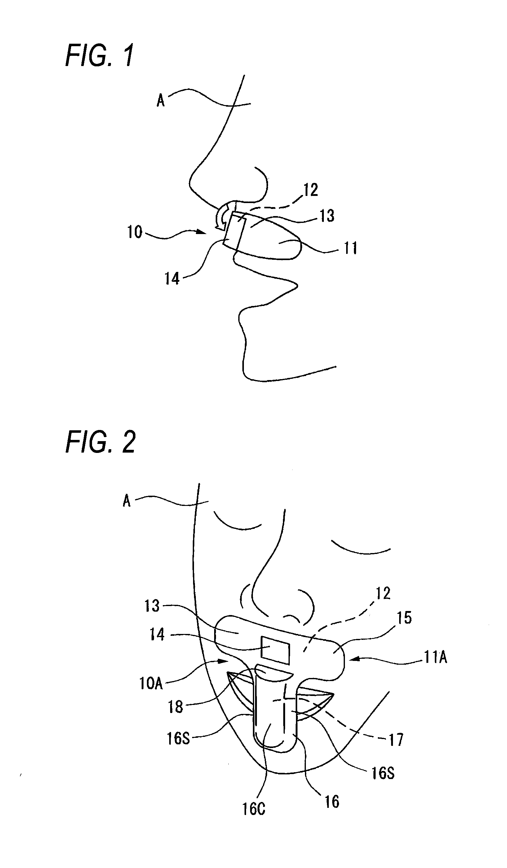
[0036]Hereinafter, embodiments of the CO2 sensor and CO2 measuring apparatus of the invention will be described with reference to the accompanying drawings. In the figures, the identical components are denoted by the same reference numerals, and duplicated description will be omitted. FIG. 1 shows the CO2 sensor of the invention. The CO2 sensor 10 has a mounting member 11 configured by a tape or sheet which is substantially identical in configuration to a backing strip (a tape) of an adhesive bandage with a pack, and which has an elongated shape. An adhesive agent is applied to a first surface 12 through which the mounting member 11 is to be stuck to a living body A.
[0037]A sensing portion 14 is disposed in a middle portion of a second surface 13 which is opposite to the first surface 12 of the mounting member 11. The sensing portion 14 changes in color in accordance with the CO2 partial pressure in the expiration. For example, the sensing portion can be configured by causing a chem...
second embodiment
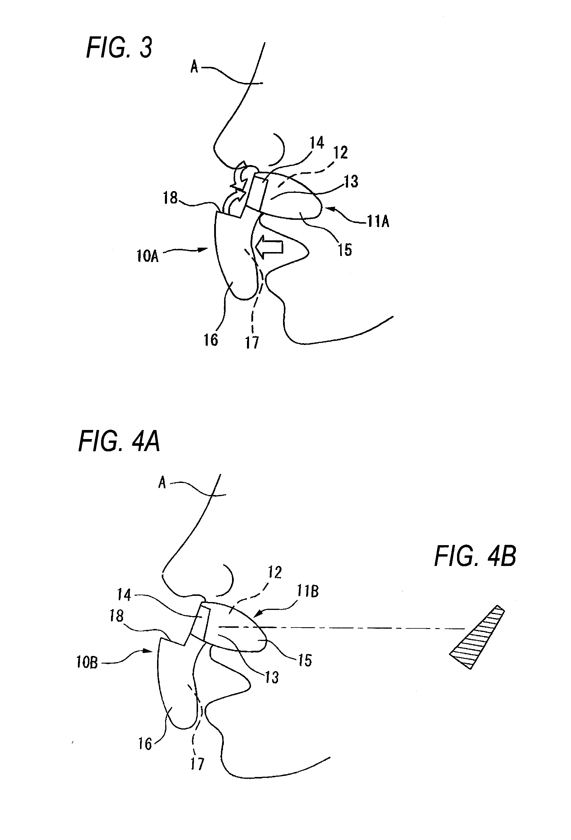
[0039]FIGS. 2 and 3 show the configuration of a CO2 sensor 10A of a A mounting member 11A of the CO2 sensor 10A has: an adhesive portion 15 which longitudinally extends about the philtrum in a band-like manner above the upper lip; and a mouth cover 16 which is integrated with the adhesive portion 15, which has a rectangular or oval plan shape, and which is formed so as to downward extend.
[0040]The adhesive portion 15 is formed by a thin resin having a backing strip-like shape. An adhesive agent is applied to the first surface 12 which is to be stuck to the living body A. The sensing portion 14 is stuck to a middle portion of the second surface 13 which is opposite to the first surface 12.
[0041]The mouth cover 16 may be formed by a resin which is thicker than the adhesive portion 15, and is disposed in a state where the cover hangs substantially perpendicularly from the adhesive portion 15 toward the mouth. The mouth cover 16 is configured so that the cover extends vertically while ...
fourth embodiment
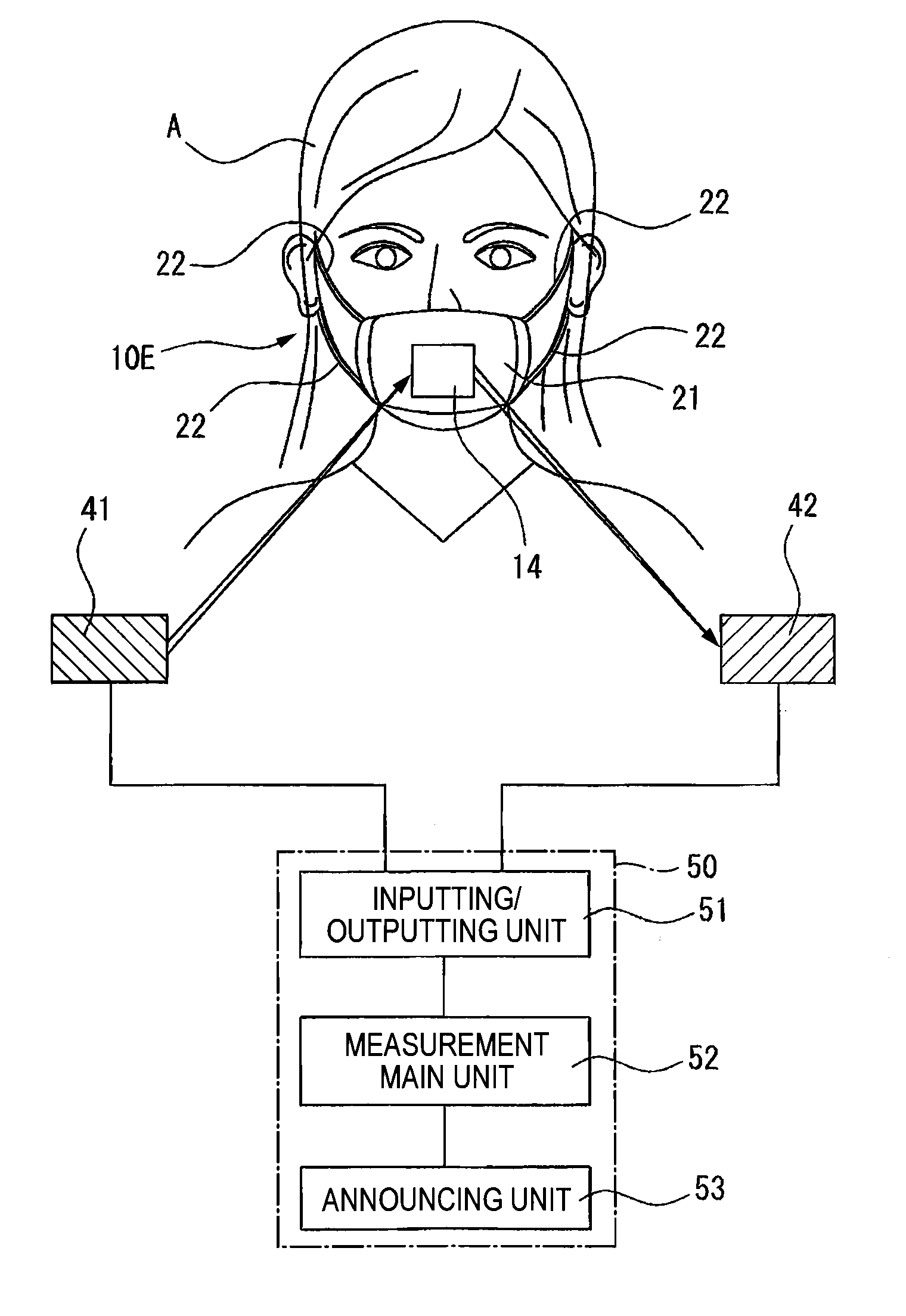
[0047]FIG. 7 shows a CO2 sensor 10E of a The CO2 sensor 10E has: a mask 21 which is configured by an air permeable sheet such as a woven fabric or a non-woven fabric, and which functions as a mounting member; and the sensing portion 14 which has been described above. The mask 21 has a plan shape which is substantially rectangular. Strings 22 which are to be looped over the ears to hold the mask 21 elongate from two sides which, when the mask 21 is attached, are located on the cheeks, respectively. The strings 22 can be adjusted in length so that, when the mask 21 is attached by the strings 22, the sensing portion 14 is located in front of the mouth and the nose. The air resistance of the air permeable sheet constituting the mask 21 is set to 4 mmH20 / cm2 or less.
[0048]According to the embodiment, cardiopulmonary resuscitation can be executed in a state where the CO2 sensor 10E is attached to the living body (patient) A, and the situation such as that the living body (patient) A resu...
PUM
 Abstract
Description
Claims
Application Information