Slide Top Shed

a shed and slide technology, applied in the field of enclosures, can solve the problems of consuming a great deal of floor space in a garage, difficult to extrude conduits in long sections for structural panels, and the like, and achieve the effects of saving wasted materials, convenient assembly, and convenient assembly

Active Publication Date: 2013-01-03
SUNCAST TECH
View PDF1 Cites 24 Cited by
  • Summary
  • Abstract
  • Description
  • Claims
  • Application Information

AI Technical Summary

Benefits of technology

[0010]The present invention provides a system or kit which includes plastic components which can be readily assembled to form a structure with the use of a minimal number of tools. The components are precut so that measurements and cutting of the component materials are eliminated. This leads to a savings in wasted materials. The components are readily assembled using conventional fasteners and simple hand tools. The components have preformed notches and tabs in order to facilitate assembly of the components without the requirement for measurements. This assures that the components will be assembled correctly and eliminates the opportunity for inaccurate measurements and incorrect assembly. The enclosure is provided with a sliding roof panel and pivoting doors which permit easy access to the interior of the enclosure.

Problems solved by technology

Typically, items such as lawn mowers, garden tillers, snow blowers, wheel barrows, shovels, rakes, brooms and the like consume a great deal of floor space in a garage.
This results in the homeowner parking his / her vehicles outside of the garage.
Due to the nature of the manufacturing process, the conduits are difficult to extrude in long sections for structural panels.
However, wall panels utilizing connectors are vulnerable to buckling under loads and may have an aesthetically unpleasing appearance.
Moreover, roof loads from snow and the like may cause such walls to bow outwardly due to the clearances required between the connectors and the internal bores of the conduits.
Such prior art systems, while working well, have not met all of the needs of consumers to provide the structural integrity required to construct larger sized structures.
A further problem is that the walls formed by the panels must tie into the roof and floor in such a way as to unify the entire structure.
There are also commercial considerations that must be satisfied by any viable structure assembly system or kit; considerations which are not entirely satisfied by the state of the art products.

Method used


Image

  • Slide Top Shed
  • Slide Top Shed
  • Slide Top Shed

Examples


Embodiment Construction

[0072]While the present invention is susceptible of embodiment in various forms, there is shown in the drawings and will hereinafter be described a presently preferred, albeit not limiting, embodiment with the understanding that the present disclosure is to be considered an exemplification of the present invention and is not intended to limit the invention to the specific embodiments illustrated.

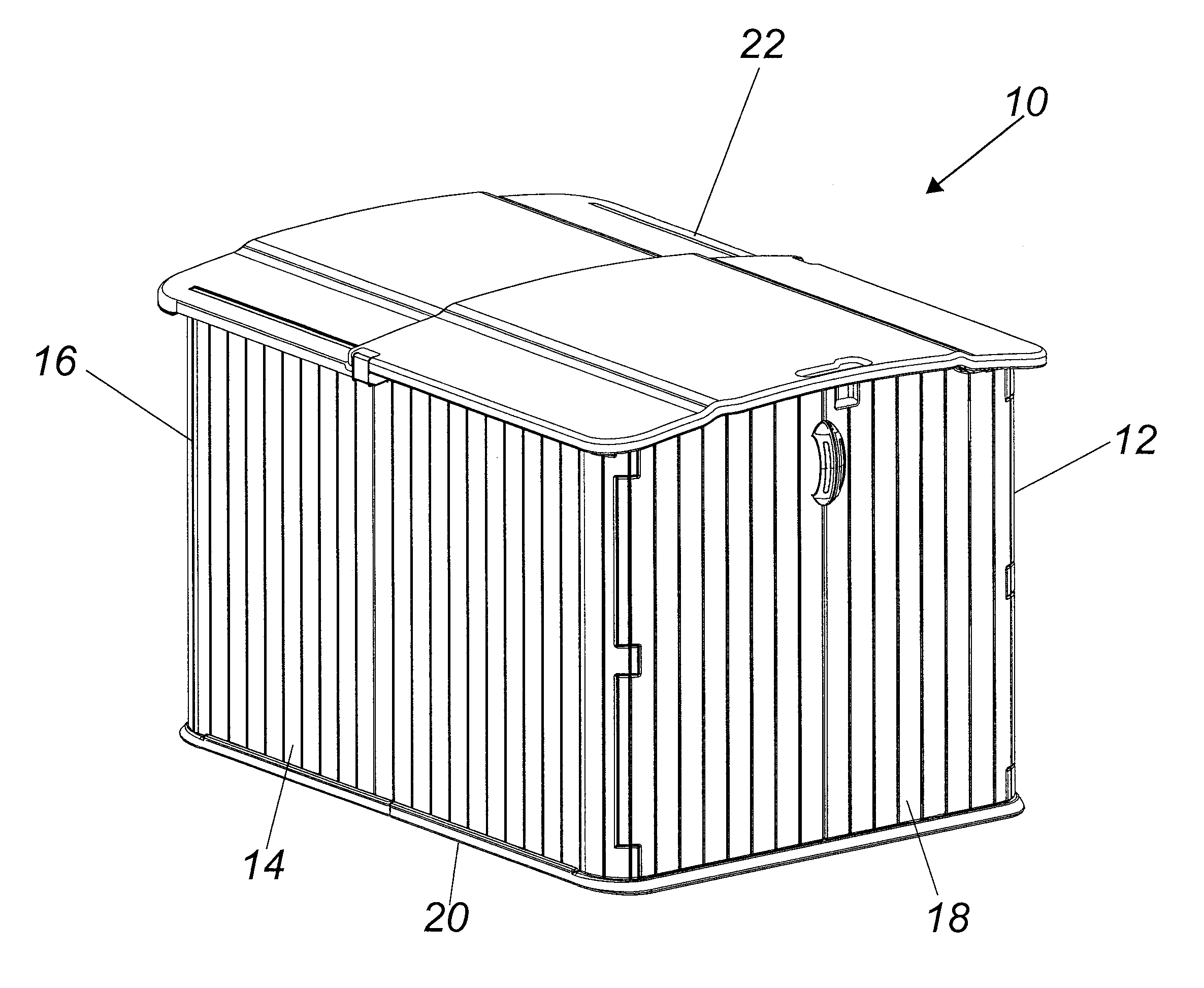
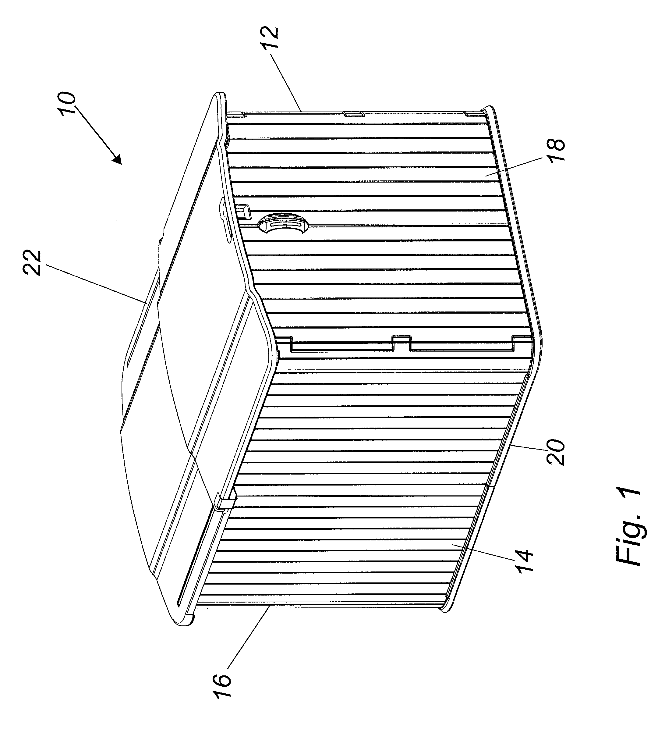
[0073]FIGS. 1-35, which are now referenced, illustrate perspective and exploded views of a system or kit for the assembly of a preferred embodiment of the present invention. A utility enclosure or shed is generally illustrated at 10 in FIG. 1. The enclosure or shed 10 includes a right side wall 12, a left side wall 14, a rear wall 16, doors 18, a floor 20, and a roof 22. The right side wall includes a right side front wall 24 and a right side rear wall 26 (FIGS. 3 and 4). The left side wall includes a left side front wall 28 and a left side rear wall 30 (FIGS. 6 and 7). A rear wall is identi...


PUM


Abstract

The present invention provides a system or kit which includes plastic components which can be readily assembled to form a structure with the use of a minimal number of tools. The components are precut so that measurements and cutting of the component materials is eliminated. This leads to a savings in wasted materials. The components are readily assembled using conventional fasteners and simple hand tools. The components have preformed notches and tabs in order to facilitate assembly of the components without the requirement for measurements. This assures that the components will be assembled correctly and eliminates the opportunity for inaccurate measurements and incorrect assembly. The enclosure is provided with a sliding roof panel and pivoting doors which permit easy access to the interior of the enclosure.

Description

CROSS REFERENCE TO RELATED APPLICATIONS[0001]This application is related to U.S. Pat. No. 7,543,411, issued Jun. 9, 2009, entitled “LOW PROFILE PLASTIC PANEL ENCLOSURE” and to U.S. patent application Ser. No. 12 / 942,679, filed Nov. 9, 2010, entitled “COMBO WOOD AND PLASTIC MODULAR STORAGE SHED”, the entireties of which are incorporated herein by reference.FIELD OF THE INVENTION[0002]This invention relates generally to enclosures, such as utility or garden sheds, constructed of plastic materials. More specifically, the present invention relates to an enclosure having walls, a roof, doors and a floor made from blow molded plastic materials.BACKGROUND OF THE INVENTION[0003]Utility sheds are a necessity for lawn and garden maintenance, as well as general all-around home storage space. Typically, items such as lawn mowers, garden tillers, snow blowers, wheel barrows, shovels, rakes, brooms and the like consume a great deal of floor space in a garage. This results in the homeowner parking...

Claims


Application Information

Patent Timeline
Patent Type & Authority Applications(United States)
IPC IPC(8): E04H1/00
CPCE04H1/1205E04B7/166E04B1/34321
Inventor UFFNER, MICHAELVOGLER, MICHAEL R.
Owner SUNCAST TECH
Why Eureka
Try Eureka