Hybrid Cooling System

a hybrid cooling and cooling system technology, applied in the direction of trickle coolers, steam/vapor condensers, lighting and heating apparatus, etc., can solve the problems of low water-saving ability, high investment cost of systems, limited application, etc., and achieve the effect of quick enhancement of cooling capacity and improved operation flexibility of hybrid cooling systems

Inactive Publication Date: 2013-01-03
GEA EGI ENERGIAGAZDALKODASI ZRT
View PDF5 Cites 12 Cited by
  • Summary
  • Abstract
  • Description
  • Claims
  • Application Information

AI Technical Summary

Benefits of technology

[0011]In addition to the common condenser, the integration of wet and dry cooling circuits is also possible through the application of water-water heat exchangers. By combining these approaches, the operational flexibility of hybrid cooling systems can be improved. This is because certain water-water heat exchangers are not only cheaper than a surface condenser, but they also enable a very quick enhancement of cooling capacity as a function of additional water availability, even including changes within an hour.

Problems solved by technology

The application of this system—in addition to the extra cost of required additional water—entails environmental problems, like, for example, the negative impact of the emitted high volume of vapour on the microclimate, icing of the roads nearby in winter-time, as well as the deposition of the water saturated with contaminations that must be drained from the cooling water circuit.
These systems require a much higher investment cost and their application is limited by the lower summer output.
One such frequently applied hybrid system is the plume abatement hybrid cooling, which eliminates the disadvantages of wet cooling systems regarding the intensive emission of vapour, although it has a low water-saving ability.
However, due to the single circuit solution, the same cooling water is circulated in the dry air-cooled tubes as taken on the wet cooler fill, which is considered as being contaminated from the aspect of air-cooled heat exchangers.
It is a further disadvantage that the extended number and length of tubes in the air cooler make their cleaning difficult.
Using the known hybrid cooling system, all this also limits the ability of accomplishing a substantial water-saving by increasing the air cooler surface.

Method used


Image

  • Hybrid Cooling System
  • Hybrid Cooling System
  • Hybrid Cooling System

Examples


Embodiment Construction

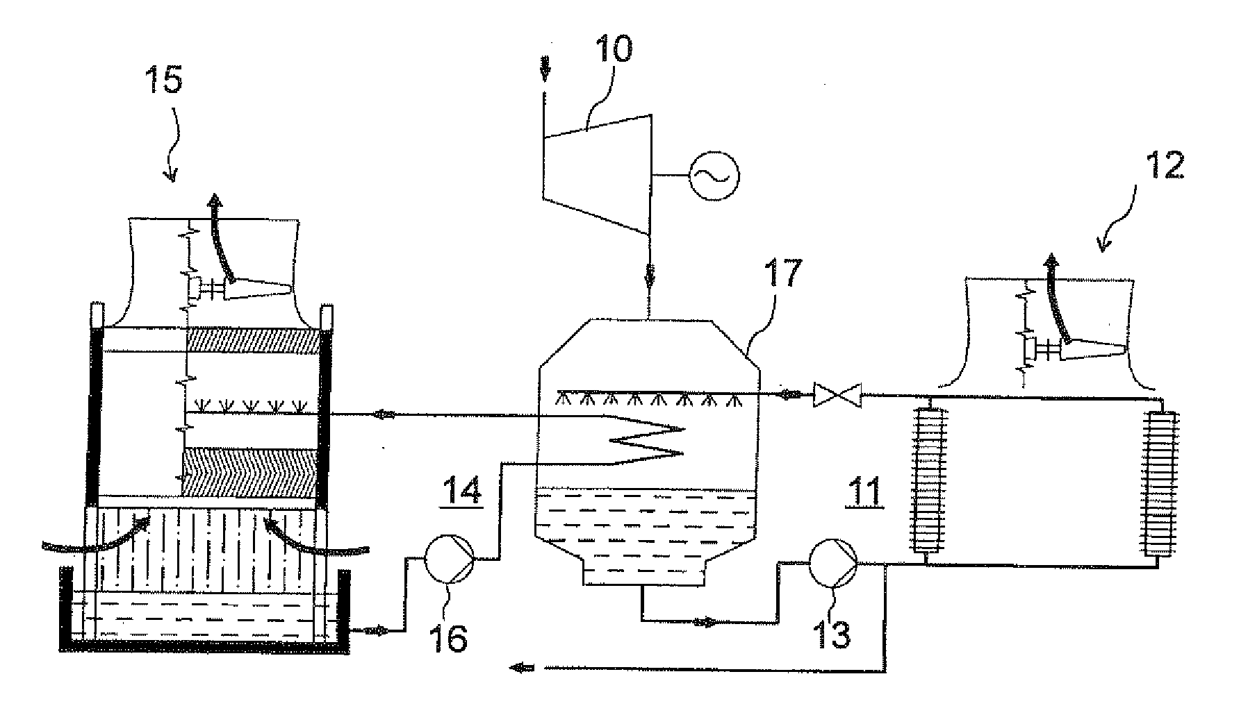
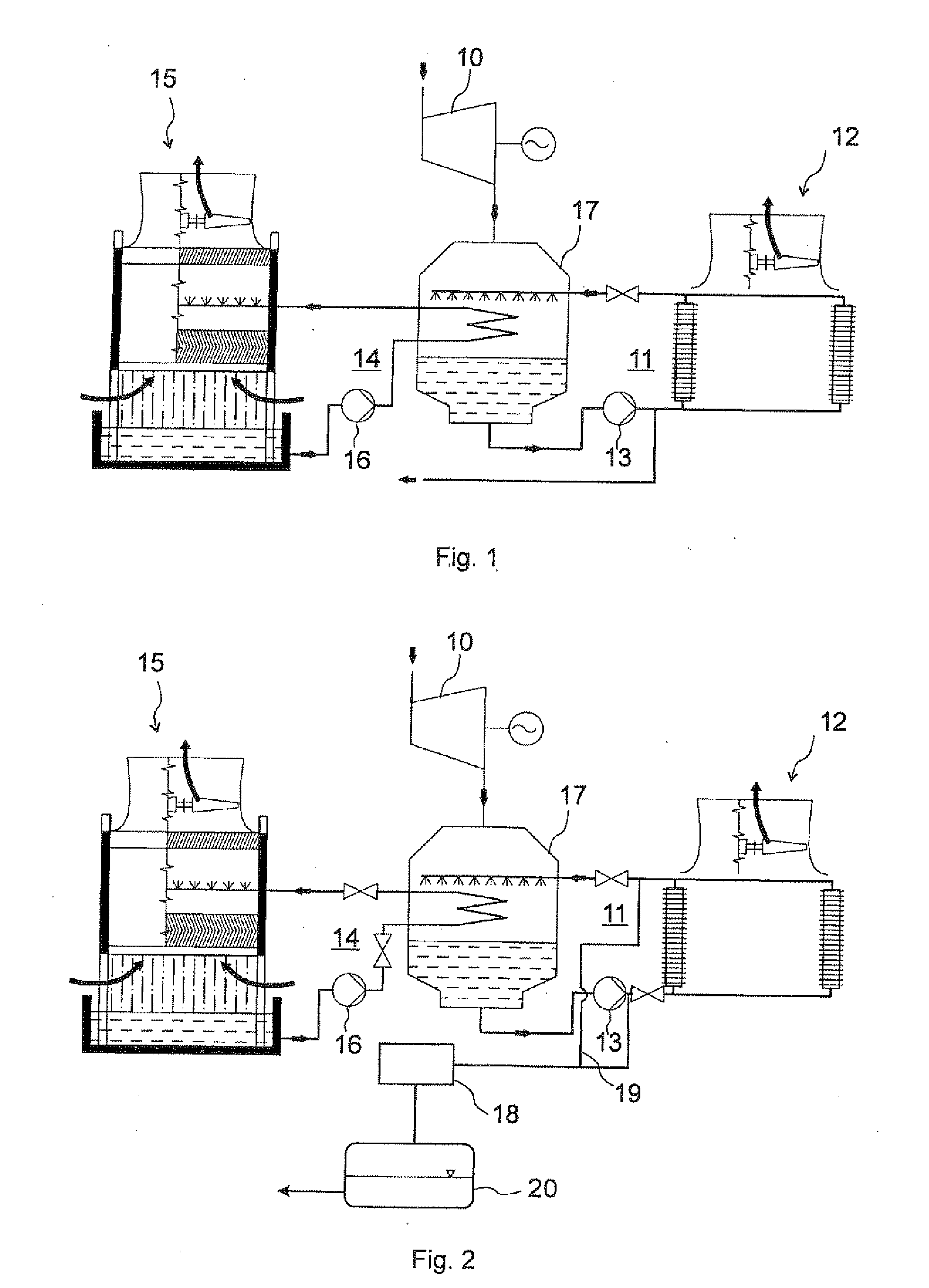
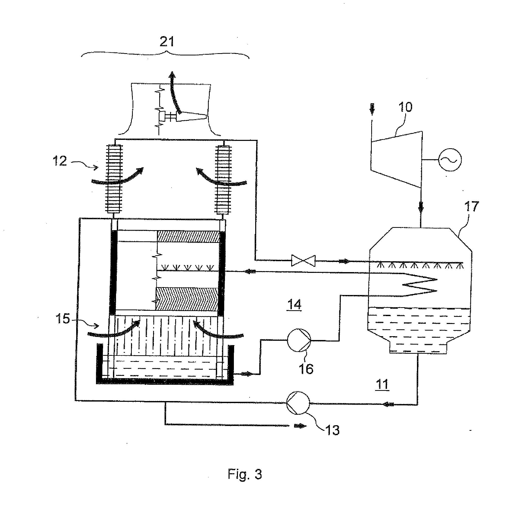
[0005]The object of our invention is to provide a dry / wet, i.e. hybrid cooling system which is exempt from the disadvantages of prior art solutions. The object of the invention is especially to create a hybrid cooling system, which combines the advantages of dry and wet cooling, while entailing no extra maintenance requirements. It is a further object to make use of other benefits offered by the combined use of dry and wet cooling, as well as the creation of a hybrid cooling system in which the proportion of dry and wet sections can be altered arbitrarily depending on the environmental parameters and actual circumstances.

[0006]Accordingly, the invention is a hybrid cooling system defined in claim 1. Preferred embodiments of the invention are defined in the dependent claims.

[0007]An important idea of the solution according to the invention is that instead of a single water circuit, separate water circuits are to be applied for the wet cooling and the dry cooling. As a preferred embod...


PUM


Abstract

The invention is a hybrid cooling system for condensing the exhaust steam of a steam turbine (10), which cooling system comprises a dry cooling circuit (11), a dry air-cooled unit (12) performing heat dissipation of cooling water flowing therein, and a wet cooling circuit (14) and a wet cooled unit (15) performing heat dissipation of the cooling water flowing therein. According to the invention, the cooling water flowing in the dry cooling circuit (11) is separated from the cooling water flowing in the wet cooling circuit (14), and the dry and wet cooling circuits (11, 14) are connected to a common condenser.

Description

TECHNICAL FIELD[0001]The present invention relates to water-saving dry / wet cooling systems, i.e. to hybrid cooling systems for use in power plants and in other industrial cyclical processes.BACKGROUND ART[0002]In prior art, the most widely used power plant and industrial cooling system is the so-called wet cooling system, in which the cooling water is allowed to evaporate freely to the environment. The application of this system—in addition to the extra cost of required additional water—entails environmental problems, like, for example, the negative impact of the emitted high volume of vapour on the microclimate, icing of the roads nearby in winter-time, as well as the deposition of the water saturated with contaminations that must be drained from the cooling water circuit. At the same time, there are known dry or in other words air cooling systems, which absolutely eliminate water consumption and the associated environmental damage, in which the cooling water is circulating in a cl...

Claims


Application Information

Patent Timeline
Patent Type & Authority Applications(United States)
IPC IPC(8): F28D15/00F28F27/00
CPCF28B5/00F01K9/003F28C1/14F28B9/06Y02B30/70
Inventor SZABO, ZOLTANLUDVIG, LASZLOBALOGH, ANDRAS
Owner GEA EGI ENERGIAGAZDALKODASI ZRT
Why Eureka
Try Eureka