
Variable speed drive system

Active Publication Date: 2013-01-03
FRANKLIN ELECTRIC CO INC
View PDF2 Cites 13 Cited by
  • Summary
  • Abstract
  • Description
  • Claims
  • Application Information

AI Technical Summary

Benefits of technology

The patent describes a method for improving the performance of a motor by controlling the voltage and driving voltage. The control voltage is designed to reduce the motor's torque and speed ripple, while maintaining the driving voltage's crest factor and total harmonic distortion within acceptable limits. The method can also reduce acoustic noise and fluid pressure ripple associated with the motor's operation. Overall, the method aims to enhance the motor's performance by reducing its vibrations and noise.

Problems solved by technology

However, many single phase systems currently in operation were not designed to operate at a variable speed and may not be capable of doing so.
In many instances, variable speed control of single phase motors magnifies the perceived acoustic noise generated by torque pulsations making it unacceptable to some users.

Method used


Image

  • Variable speed drive system
  • Variable speed drive system
  • Variable speed drive system

Examples


Embodiment Construction

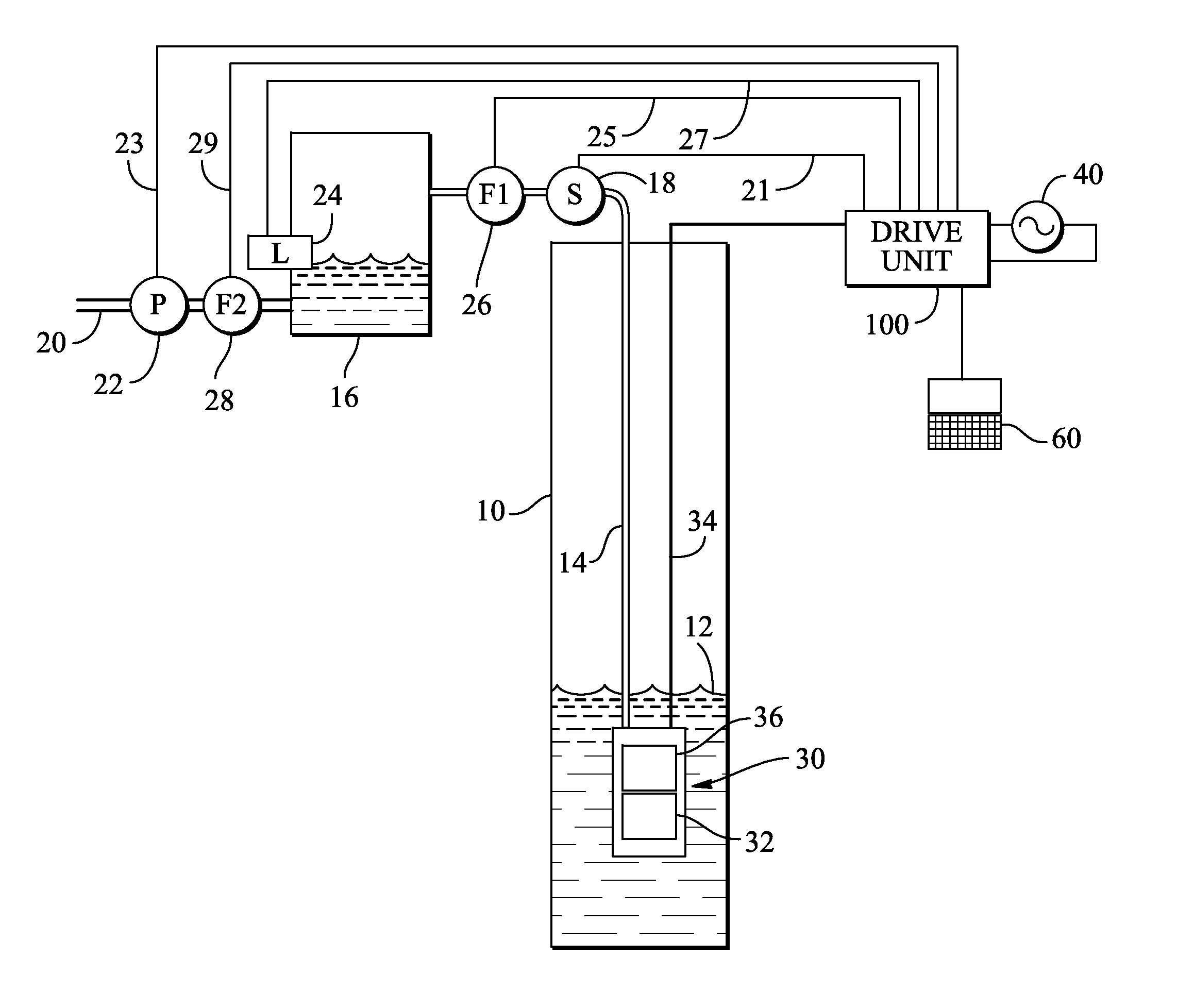
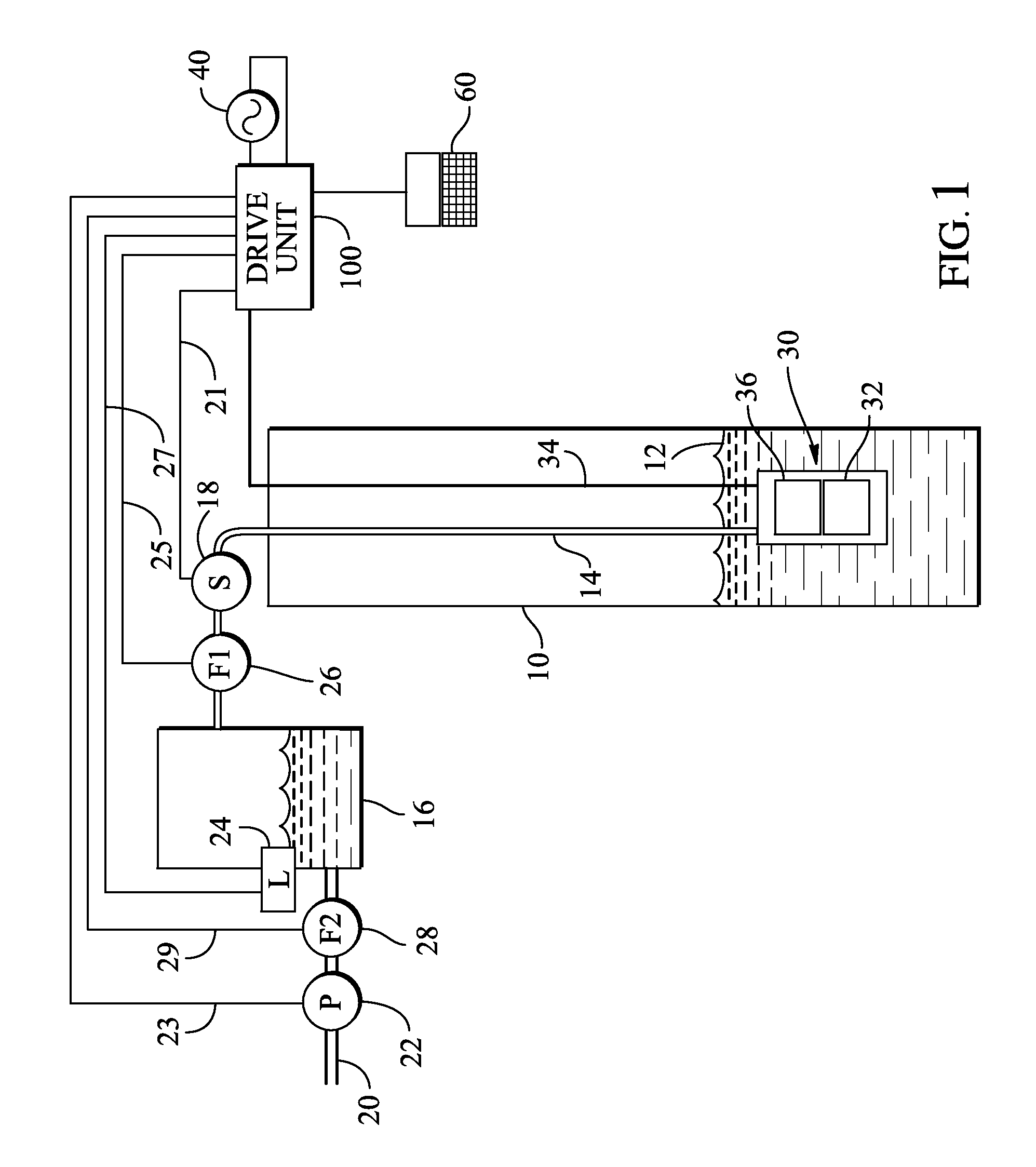
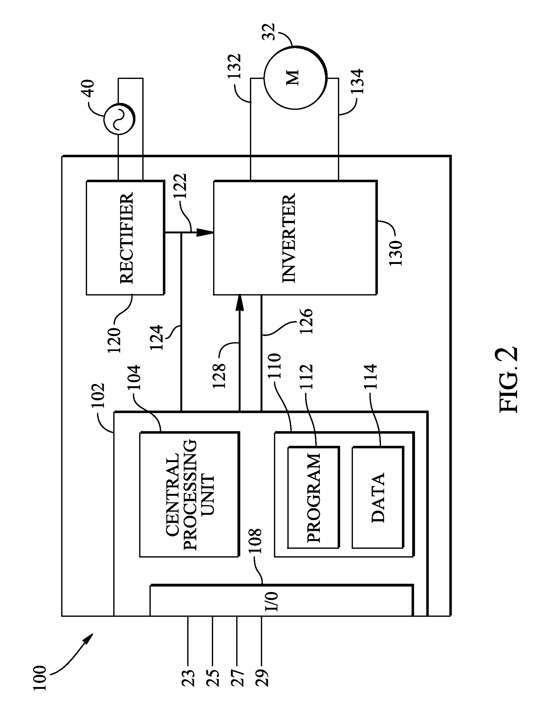
[0028]For the purposes of promoting an understanding of the principles of the invention, reference will now be made to the embodiments illustrated in the drawings, which are described below. The embodiments disclosed below are not intended to be exhaustive or limit the invention to the precise form disclosed in the following detailed description. Rather, the embodiments are chosen and described so that others skilled in the art may utilize their teachings. It will be understood that no limitation of the scope of the disclosure is thereby intended. The invention includes any alterations and further modifications in the illustrated devices and described methods and further applications of the principles of the invention which would normally occur to one skilled in the art to which the invention relates.

[0029]The invention disclosed herein relates to improved methods and systems for driving single phase motors and loads. For any electrical load on a single phase power supply, the insta...


PUM


Abstract

This disclosure relates to a variable speed drive for driving a single phase motor. The variable speed drive generates enhanced motor voltages including harmonic components configured to reduce torque pulsations.

Description

CROSS-REFERENCE TO RELATED APPLICATIONS[0001]This application claims the benefit of U.S. Provisional Patent Application Ser. No. 61 / 313,576 entitled VARIABLE SPEED DRIVE SYSTEM filed on Mar. 12, 2010, which is expressly incorporated by reference herein in its entirety.FIELD OF THE DISCLOSURE[0002]A system and method for driving a motor, and more particularly a system and method for controlling an operating characteristic of the motor.BACKGROUND OF THE DISCLOSURE[0003]Fluid supply systems use motors to drive pumps and transfer fluids from supply reservoirs, such as wells, to demand reservoirs, such as tanks. A sensor measures a characteristic of the fluid, and a controller controls operation of the motor. In some systems, the controller measures a level of the fluid in a tank and controls operation of the motor to maintain the level within a range. When the level reaches the low end of the range, the controller turns the motor on and keeps it on until the level reaches the high end o...

Claims


Application Information

Patent Timeline
IPC IPC(8): H02P27/08
CPCH02P23/0077
Inventor SPREEN, JAMES H.NORTHUP, JONATHAN D.
Owner FRANKLIN ELECTRIC CO INC
Learn More