Obstacle detection apparatus and obstacle detection program

a technology for obstacle detection and obstacle detection, applied in the direction of measuring devices, using reradiation, instruments, etc., can solve the problems of false detection with respect, and achieve the effect of reducing false detection of obstacles

Active Publication Date: 2013-01-03
HONDA ELESYS CO LTD
View PDF24 Cites 62 Cited by
  • Summary
  • Abstract
  • Description
  • Claims
  • Application Information

AI Technical Summary

Benefits of technology

[0055]According to this program, by determining the presence or absence of an obstacle based on the image captured by the camera, with regard to the obstacle in which it is determined that the false detection characteristic is present

Problems solved by technology

As described above, the vehicle-mounted radar has a problem that false detection occurs with

Method used


Image

  • Obstacle detection apparatus and obstacle detection program
  • Obstacle detection apparatus and obstacle detection program
  • Obstacle detection apparatus and obstacle detection program

Examples


first embodiment

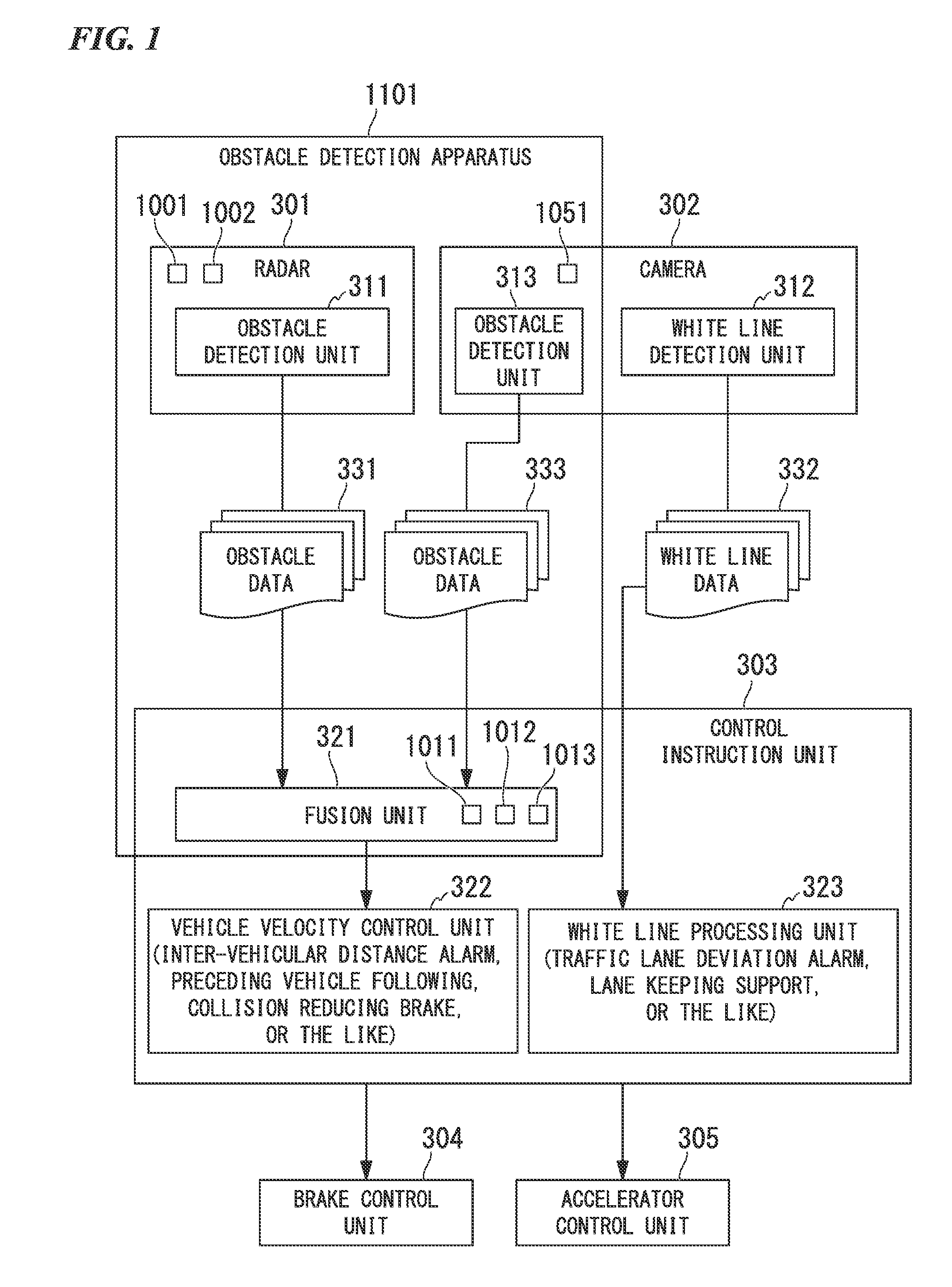
[0116]FIG. 1 is a block diagram illustrating a configuration example of a vehicle control system which includes an obstacle detection apparatus 1101 according to a first embodiment of the invention.

[0117]The vehicle control system according to the first embodiment includes a radar 301, a camera 302, a control instruction unit 303, a brake control unit 304, and an accelerator control unit 305.

[0118]The radar 301 includes a transmission antenna 1001, a reception antenna 1002, and an obstacle detection unit 311 which outputs obstacle data 331.

[0119]The camera 302 includes an imaging unit 1051 which captures an image, a white line detection unit 312 which outputs white line data 332, and an obstacle detection unit 313 which outputs obstacle data 333.

[0120]The control instruction unit 303 includes a fusion unit 321, a vehicle velocity control unit 322, and a white line processing unit 323.

[0121]The fusion unit 321 includes a false detection determination unit 1011 which has a function of...

second embodiment

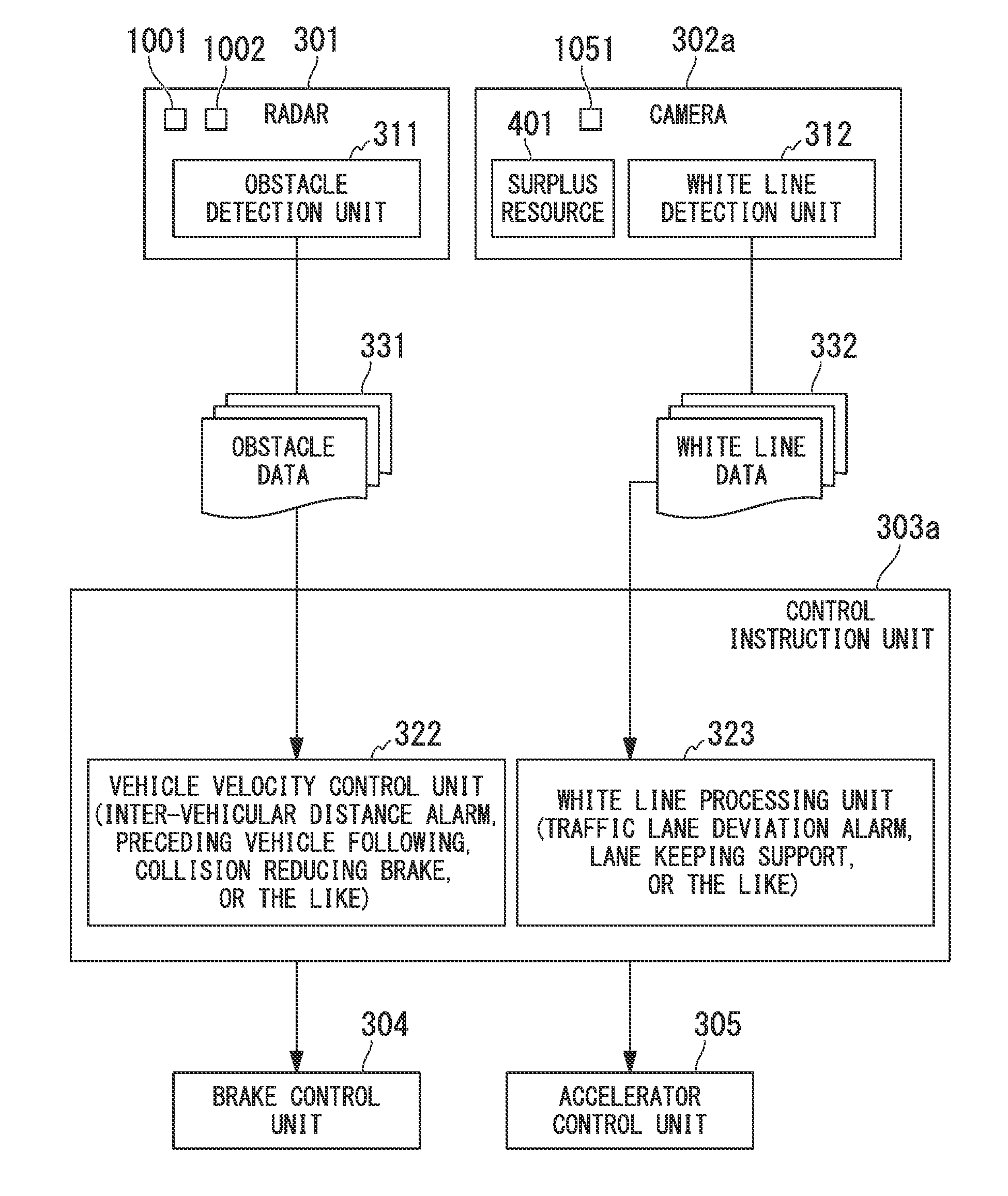
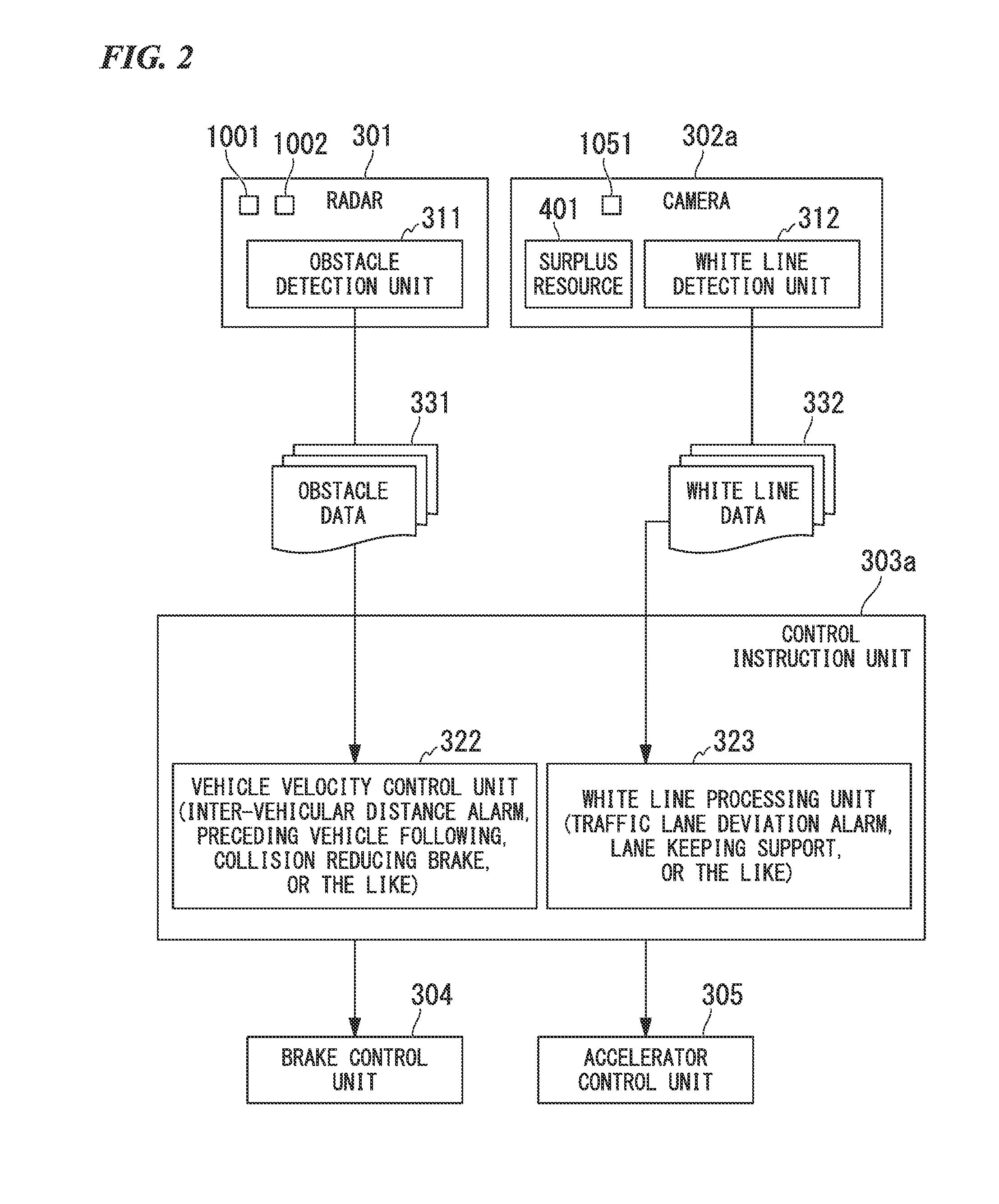
[0216]FIG. 4 is a block diagram illustrating a configuration example of a vehicle control system which includes an obstacle detection apparatus 1102 according to a second embodiment of the invention.

[0217]The vehicle control system according to the second embodiment includes a radar 501, a camera 502, a control instruction unit 503, a brake control unit 504, and an accelerator control unit 505.

[0218]The radar 501 includes a transmission antenna 1021, a reception antenna 1022, and an obstacle detection unit 511 which outputs obstacle data 531.

[0219]The camera 502 includes an imaging unit 1052 which captures an image, a white line detection unit 512 which outputs white line data 532, and an obstacle correction unit 513.

[0220]The control instruction unit 503 includes a vehicle velocity control unit 521 and a white line processing unit 522.

[0221]The vehicle velocity control unit 521 includes an inter-vehicular distance alarm function, a preceding vehicle following function, a collision ...

embodiment 1-1

[0284]Hereinafter, an electronic scanning type radar device (FMCW type millimeter-wave radar) according to an embodiment of the invention according to the first related art will be described with reference to the accompanying drawings. FIG. 12 is a block diagram illustrating a configuration example of the embodiment.

[0285]In the figure, an electronic scanning type radar device according to the embodiment 1-1 includes reception antennas 11 to 1n, mixers 21 to 2n, a transmission antenna 3, a distributor 4, filters 51 to 5n, a SW (switch) 6, an ADC (A / D converter) 7, a control unit 8, a triangular wave generating unit 9, a VCO (Voltage Controlled Oscillator) 10, and a signal processing unit 20.

[0286]The signal processing unit 20 includes a memory 21, a reception intensity calculation unit 22, a DBF detection unit 23, a distance detection unit 24, a velocity detection unit 25, a direction settling unit 26, a target linking unit 27, an elevation-view structure determination unit 28 and a...


PUM


Abstract

An obstacle detection apparatus includes a transmission antenna transmitting radio waves, a reception antenna receiving radio waves transmitted to and reflected by an obstacle, an obstacle detection unit configured to detect the obstacle based on the received radio waves, a false detection determination unit configured to determine presence or absence of a false detection characteristic, which is set in advance, with regard to the detected obstacle, a camera capturing an image, and an obstacle existence determination unit configured to determine, based on the image captured by the camera, presence or absence of the obstacle on which it is determined that the false detection characteristic is present.

Description

CROSS-REFERENCE TO RELATED APPLICATIONS[0001]Priority is claimed on Japanese Patent Application No. 2011-133681, filed Jun. 15, 2011, the contents of which are entirely incorporated herein by reference.BACKGROUND OF THE INVENTION[0002]1. Field of the Invention[0003]The present invention relates to an obstacle detection apparatus and an obstacle detection program.[0004]2. Background Art[0005]In vehicles, a vehicle-mounted radar is used in a vehicle velocity control system such as an inter-vehicle distance alarm system, a preceding vehicle following system or a collision reducing brake system. As the radar, a millimeter-wave radar is used, for example. Furthermore, the radar is generally mounted in a front portion of a vehicle.[0006]FIG. 5 illustrates an example of a situation where an obstacle 603 is present in front of a host vehicle 601 mounted with a radar 602 in a front portion of a vehicle body. In this example, the front obstacle 603 is another vehicle. Furthermore, in this exa...

Claims


Application Information

Patent Timeline
IPC IPC(8): G01S13/86G01S13/931
CPCG01S13/345G01S13/867G01S13/931G01S2013/9375G01S2013/9353G01S2013/9321G01S2013/9342G01S2013/9346G01S2013/935G01S2013/462G01S2013/9318G01S2013/9319G01S2013/93185G01S2013/93271G01S2013/932
Inventor KAMBE, TAKESHISEKINE, KAZUYUKI
Owner HONDA ELESYS CO LTD
Why Eureka
Try Eureka