Transmission power adjustment method in wireless communication system and base station

a wireless communication system and transmission power technology, applied in the field of wireless communication technology, can solve the problems of inability to make optimum transmission power control, inability to add usable frequency easily, and inability to achieve optimum control similarly, so as to reduce the total transmission power of the base station, increase frequency utilization efficiency, and reduce the effect of base station siz

Inactive Publication Date: 2013-01-03
HITACHI LTD
View PDF4 Cites 9 Cited by
  • Summary
  • Abstract
  • Description
  • Claims
  • Application Information

AI Technical Summary

Benefits of technology

[0011]According to the present invention, since necessary power for terminals can be secured while suppressing total transmission power of base station and FFR technique can be realized with increased utilization efficiency of frequency, base station can be made smaller and communication capacity can be increased.

Problems solved by technology

Communication systems can increase communication capacity if frequency can be added although since frequency resources allocated to communication systems are limited, it is not possible to add usable frequency easily.
Transmission power of FFR is fixed and accordingly optimum transmission power control cannot be made on the condition that transmission power is limited.
Further, in the method described in the patent document of W-A-2009-21787, transmission power is variable, although frequency scheduling considering transmission power is not performed and accordingly there is a case where optimum control cannot be made similarly.

Method used


Image

  • Transmission power adjustment method in wireless communication system and base station
  • Transmission power adjustment method in wireless communication system and base station
  • Transmission power adjustment method in wireless communication system and base station

Examples


embodiment 1

[0031]First, configuration of a noble communication system to which the present invention is applied is described.

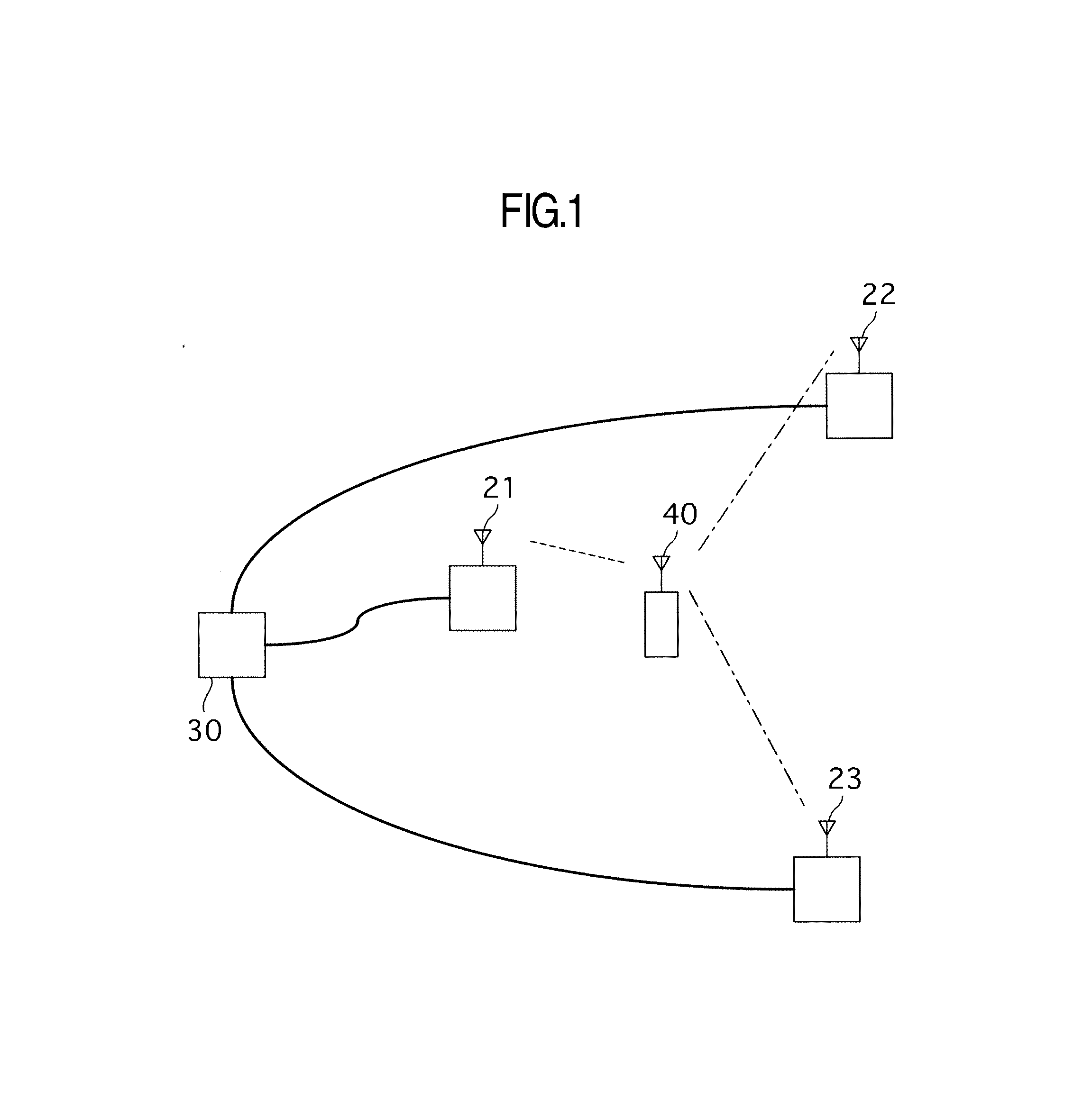
[0032]FIG. 1 is a diagram showing an example schematically illustrating a wireless communication system. Base stations 21 to 23 are connected to a core network through a core-side apparatus 30 and perform data communication. Base station 21 converts information obtained from core-side apparatus 30 into high-frequency signal and transmits it to terminal 40 as radio signal. Terminal 40 receives the radio signal and subjects it to signal processing to be converted into information, so that communication with core-side apparatus 30 is attained. On the other hand, information produced by terminal 40 is converted into high-frequency signal in terminal 40 to be transmitted to base station 21 as radio signal. The radio signal transmitted by terminal 40 and received by base station 21 is subjected to signal processing to be converted into information and the information is transm...

embodiment 2

[0068]The second embodiment 2 is now described with reference to FIG. 16. Description about parts which perform the same operation as the embodiment 1 is omitted.

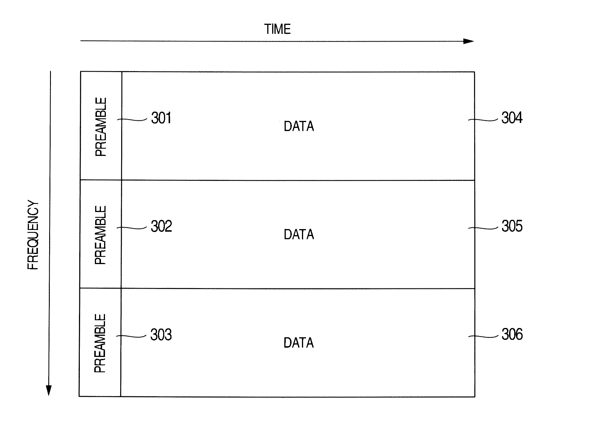
[0069]FIG. 16 is a mapping diagram for frequency axis and time axis of transmission frame of the embodiment. In the embodiment, preamble 311 is provided at the head of time axis and DATA area is divided into three frequency domains 312, 313 and 314 in one frequency group. The division into frequency domains 312, 313 and 314 is performed logically and terminals are subjected to frequency scheduling in accordance with only area indication named MAP information from base station contained in the head of DATA area. There is a case where physical arrangement is arrangement in which the above logical arrangement is dispersed within one frequency group by pseudorandom series named Perm base and accordingly logical arrangement is dispersed physically, so that only specific sub-carrier is prevented from continuously receiving interf...

embodiment 3

[0075]The embodiment 3 is now described with reference to FIG. 17. Description about parts which perform the same operation as the embodiments 1 and 2 is omitted.

[0076]FIG. 17 is a mapping diagram for frequency axis and time axis of transmission frame of the embodiment. In the embodiment, preamble 321 is provided at the head of time axis and DATA area is divided into three frequency domains 322, 323 and 324 in one frequency group. DATA areas 322, 323 and 324 and DATA area 325 are divided by time domain. The division into frequency domains 322, 323 and 324 is performed logically and terminals are subjected to frequency scheduling in accordance with only area indication named MAP information from base station contained in the head of DATA area Maximum transmission power of base station is limited by any one of total transmission power of data areas 322, 323 and 324 and transmission power of data area 325.

[0077]Algorithm of adjustment of power and operation at the time of movement of t...


PUM


Abstract

Necessary transmission power of terminals is secured while suppressing total transmission power in base station, so that FFR technology is realized with high frequency utilization efficiency to thereby realize both of compactness of base station and increase of communication capacity. Frequency resource is divided into frequency for boundary area of cell and frequency for central area of cell. Transmission power per unit frequency is fixed in the frequency for boundary area of cell and is set to be variable in the frequency for central area of cell. Transmission power per unit frequency is adjusted so as to satisfy necessary power of terminals connected to frequency for central area of cell. When it is judged that total transmission power of base station exceeds prescribed value, terminal is moved from central area to boundary area of cell, so that total transmission power is suppressed to be equal to or smaller than standard.

Description

INCORPORATION BY REFERENCE[0001]The present application claims priority from Japanese application JP2011-146953 filed on Jul. 1, 2011, the content of which is hereby incorporated by reference into this application.BACKGROUND OF THE INVENTION[0002]The present invention relates to wireless communication technology and more particularly to the technology of controlling transmission power in each frequency band in a wireless communication system of cellular type.[0003]Mobile wireless communication is required to constitute service area spreading as surface in order to communicate moving terminals with a base station, and the cellular system is generally used. In the wireless communication system of cellular system, plural base stations or antennas are distributed dispersedly and areas named cells in which wireless communication can be made are set within the range where radio waves from base stations or antennas are reached, so that the service area of wireless communication spreading a...

Claims


Application Information

Patent Timeline
Patent Type & Authority Applications(United States)
IPC IPC(8): H04W52/22
CPCH04W72/0453H04W72/121H04W52/146H04W52/44H04W52/367H04W52/283H04W52/346
Inventor OHARA, TATSUNORIKUWAHARA, MIKIOKANZAKI, HAJIMESASAYAMA, TSUKASA
Owner HITACHI LTD
Why Eureka
Try Eureka