Transmission power adjustment method in wireless communication system and base station
a wireless communication system and transmission power technology, applied in the field of wireless communication technology, can solve the problems of inability to make optimum transmission power control, inability to add usable frequency easily, and inability to achieve optimum control similarly, so as to reduce the total transmission power of the base station, increase frequency utilization efficiency, and reduce the effect of base station siz
- Summary
- Abstract
- Description
- Claims
- Application Information
AI Technical Summary
Benefits of technology
Problems solved by technology
Method used
Image
Examples
embodiment 1
[0031]First, configuration of a noble communication system to which the present invention is applied is described.
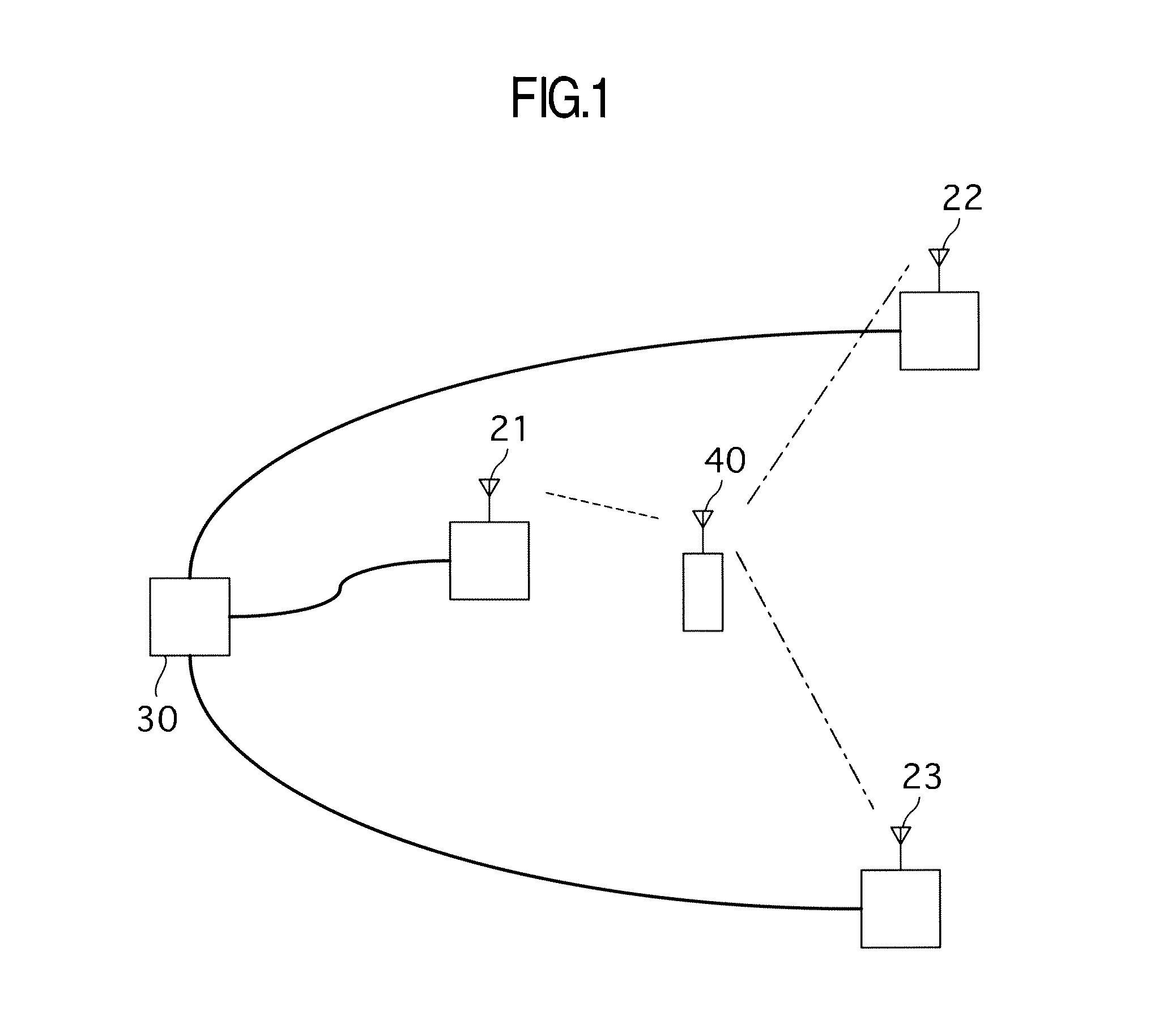
[0032]FIG. 1 is a diagram showing an example schematically illustrating a wireless communication system. Base stations 21 to 23 are connected to a core network through a core-side apparatus 30 and perform data communication. Base station 21 converts information obtained from core-side apparatus 30 into high-frequency signal and transmits it to terminal 40 as radio signal. Terminal 40 receives the radio signal and subjects it to signal processing to be converted into information, so that communication with core-side apparatus 30 is attained. On the other hand, information produced by terminal 40 is converted into high-frequency signal in terminal 40 to be transmitted to base station 21 as radio signal. The radio signal transmitted by terminal 40 and received by base station 21 is subjected to signal processing to be converted into information and the information is transm...
embodiment 2
[0068]The second embodiment 2 is now described with reference to FIG. 16. Description about parts which perform the same operation as the embodiment 1 is omitted.
[0069]FIG. 16 is a mapping diagram for frequency axis and time axis of transmission frame of the embodiment. In the embodiment, preamble 311 is provided at the head of time axis and DATA area is divided into three frequency domains 312, 313 and 314 in one frequency group. The division into frequency domains 312, 313 and 314 is performed logically and terminals are subjected to frequency scheduling in accordance with only area indication named MAP information from base station contained in the head of DATA area. There is a case where physical arrangement is arrangement in which the above logical arrangement is dispersed within one frequency group by pseudorandom series named Perm base and accordingly logical arrangement is dispersed physically, so that only specific sub-carrier is prevented from continuously receiving interf...
embodiment 3
[0075]The embodiment 3 is now described with reference to FIG. 17. Description about parts which perform the same operation as the embodiments 1 and 2 is omitted.
[0076]FIG. 17 is a mapping diagram for frequency axis and time axis of transmission frame of the embodiment. In the embodiment, preamble 321 is provided at the head of time axis and DATA area is divided into three frequency domains 322, 323 and 324 in one frequency group. DATA areas 322, 323 and 324 and DATA area 325 are divided by time domain. The division into frequency domains 322, 323 and 324 is performed logically and terminals are subjected to frequency scheduling in accordance with only area indication named MAP information from base station contained in the head of DATA area Maximum transmission power of base station is limited by any one of total transmission power of data areas 322, 323 and 324 and transmission power of data area 325.
[0077]Algorithm of adjustment of power and operation at the time of movement of t...
PUM
 Abstract
Description
Claims
Application Information
 - R&D
- Intellectual Property
- Life Sciences
- Materials
- Tech Scout
- Unparalleled Data Quality
- Higher Quality Content
- 60% Fewer Hallucinations
Browse by: Latest US Patents, China's latest patents, Technical Efficacy Thesaurus, Application Domain, Technology Topic, Popular Technical Reports.
© 2025 PatSnap. All rights reserved.Legal|Privacy policy|Modern Slavery Act Transparency Statement|Sitemap|About US| Contact US: help@patsnap.com


