Mobile base and x-ray machine mounted on such a mobile base

a mobile base and x-ray machine technology, applied in the field of mobile bases, can solve the problems of inability to move away from the patient support table or bed, the x-ray machine is not suited to an operating ward, and the stage of placing and moving the patient on the table becomes more difficul

Active Publication Date: 2013-01-03
BA HEALTHCARE
View PDF18 Cites 30 Cited by
  • Summary
  • Abstract
  • Description
  • Claims
  • Application Information

AI Technical Summary

Problems solved by technology

However, this type of X-ray machine is not suited to an operating ward.
Since these angiography machines are fixed to the ground, they cannot be moved away from the patient support table or bed at a time when the presence of the radiography system is not necessary.
Furthermore, the stages of placing and moving the patient on the table become more difficult because this bulky system cannot be moved away.
However, this type of X-ray machine has drawbacks.
Indeed, these machines are not suited to angiography procedures.
For the necessary power delivered by the X-ray tube is not sufficient to perform the angiography procedures which require excellent image quality.
Furthermore, these mobile X-ray machines do not provide for complex angular movements because the diameter of the arm that supports the tube and the detector is not big enough.
Similarly, these mobile X-ray machines do not reach sufficient rotation speeds to enable high quality 3D image reconstruction like those needed in a present-day angiography machine.
These mobile X-ray machines are also not suited to angiography procedures requiring certain automated motions needed for certain applications, especially 3D reconstruction.
Furthermore, even if the weight of such a machine is half that of an X-ray machine intended for angiography, it is still very difficult to move because of its large size and its weight (about 300 kg).
However, this type of X-ray machine has drawbacks.
Most of these systems are fixed to the ceiling around the patient's table depending on the constraints of an operations room, thus cluttering the space around the patient's table.
Consequently, owing to the space requirement of the rails fixed to the ceiling and the volume of the X-ray machine, their installation in a surgical ward as an angiography machine is quite impossible.
Furthermore, the fact of mounting an X-ray machine on the ceiling considerably increases the risk of opportunistic infection in the patient.
Indeed, these X-ray machines suspended on the ceiling are designed to be positioned above the patient or in his immediate vicinity and therefore in the immediate vicinity of the operating site thus increasing the risk of particles falling from the machine.
Furthermore, this fact of suspending the X-ray machine or machine gives rise to difficulties in cleaning and maintaining this machine properly.
Thus, it becomes impossible to mount this type of X-ray machine adapted to environments of varying sterility.
Indeed, operating rooms are constantly sterilized and the fact of having rails on which the X-ray machine slides above the patient increases the risks of nosocomial illness or septicemia owing to the difficulty of cleaning these apparatuses
However, X-ray machines of this type have drawbacks.
Indeed, the arms fitted to these robots generally have a relatively substantial space requirement for the space available in a surgical ward.
Consequently, the movement of these arms creates risks of safety for people working in a surgical ward.
Consequently, the installation of these robots as angiography machines in a surgical ward is quite impossible.

Method used


Image

  • Mobile base and x-ray machine mounted on such a mobile base
  • Mobile base and x-ray machine mounted on such a mobile base
  • Mobile base and x-ray machine mounted on such a mobile base

Examples


Embodiment Construction

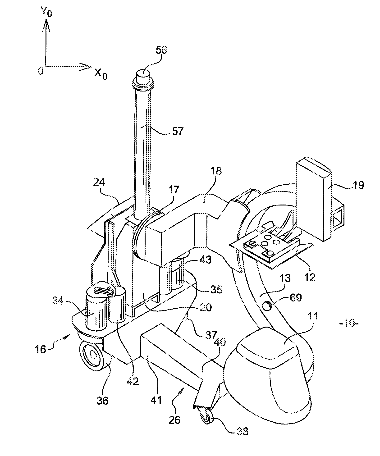
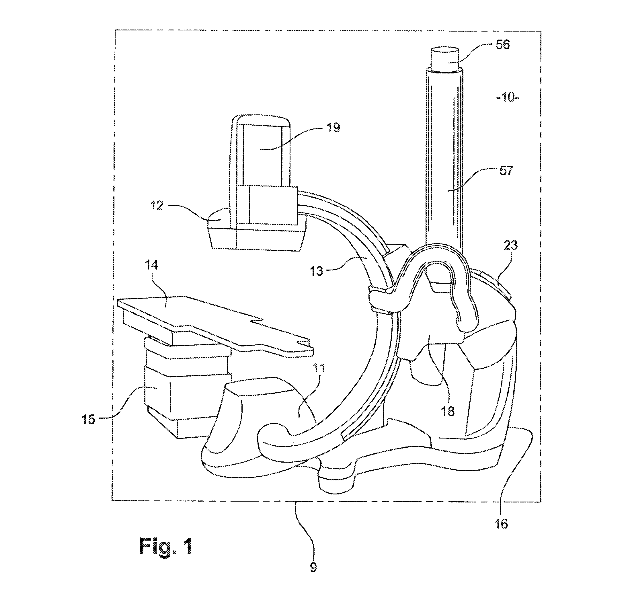
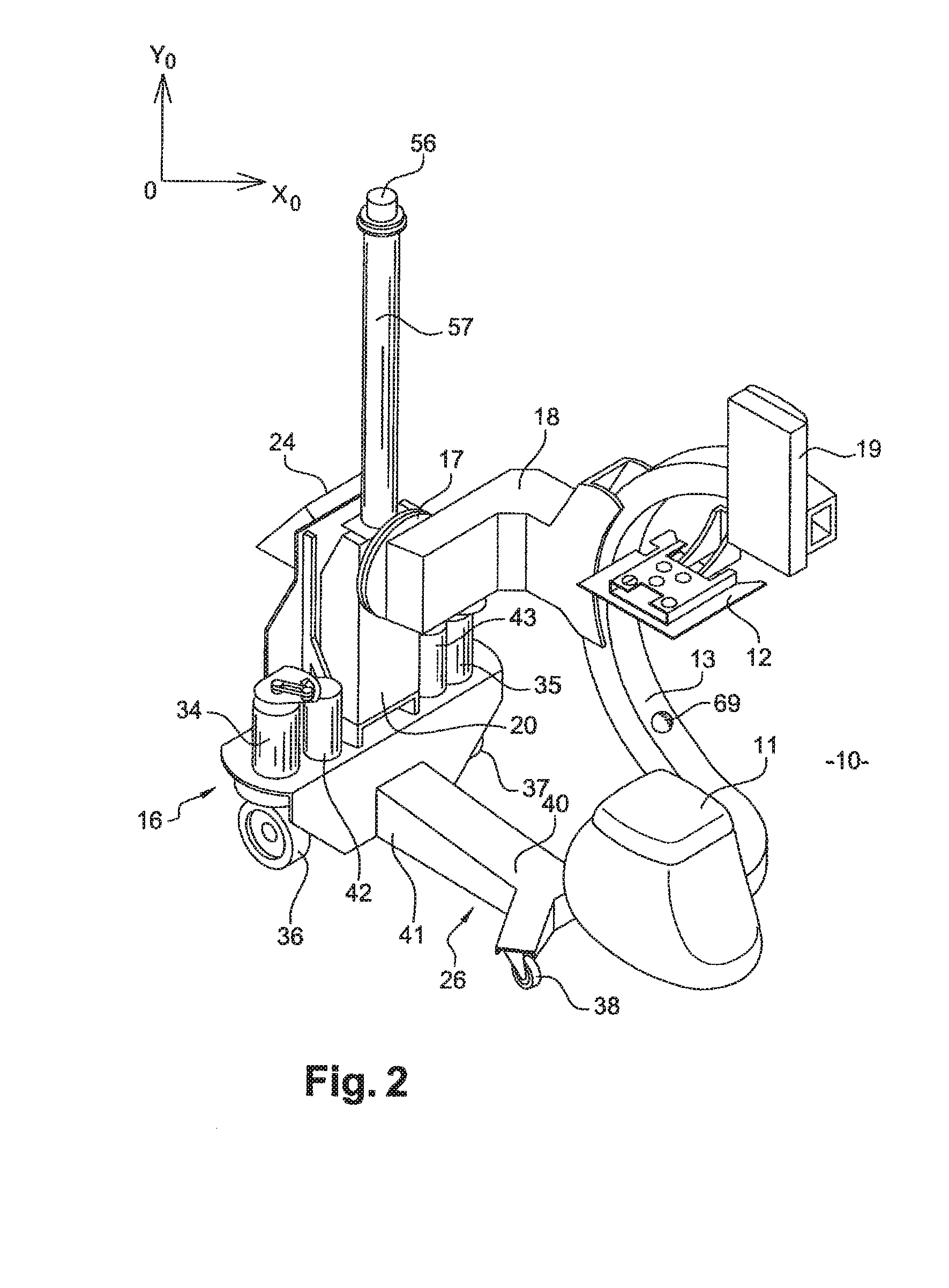
[0031]FIG. 1 shows a vascular type X-ray machine 10 in an examination room or surgical ward or hybrid room represented in the form of a frame referenced 9. The X-ray machine 10 has moving parts that can rotate in different directions around a patient. These moving parts are capable of moving in all three dimensions of a space. These moving parts are formed in general by an arm 13 comprising an X-ray tube 11, which is the X-ray source, at one of its ends and a detector 12 at another of its ends. This tube 11 is used to send an X-ray beam along a direction of emission. In general, the arm 13 is C-shaped.

[0032]The detector 12 is hooked to the arm 13 opposite the tube 11 and in the direction of emission. The X-ray tube 11 and the image detector 12 are mounted at the opposite ends of the arm 13 so that the X-rays emitted by the tube 11 are incidental to and detected by the image detector 12. The detector 12 is connected to a lift 19 used to raise and lower said detector in the direction ...


PUM


Abstract

A mobile base designed to receive an X-ray machine is provided. An X-ray machine capable of being mounted on the mobile base is also provided. The X-ray machine of the invention is configured to move using a motor-driven system associated with a navigation system. The navigation system of the invention enables the X-ray machine to be moved automatically and with precision from one position to another within an examination, hybrid or operation room. The X-ray machine is also configured for the automatic positioning of the moving parts around the patient, while at the same time keeping the region to be subjected to radiography within an X-ray beam.

Description

CROSS REFERENCE TO RELATED APPLICATIONS[0001]This is a national stage application under 35 U.S.C. §371(c) of prior-filed, co-pending PCT patent application serial number PCT / IB10 / 003012, filed on Nov. 4, 2010, which claims priority to French Patent Application Serial No. 0958556, filed on Dec. 1, 2009, the entire contents of which are incorporated herein by reference.BACKGROUND OF THE INVENTION[0002]1. Field of the Invention[0003]Embodiments of the subject matter disclosed herein generally relate to a mobile base designed to receive an X-ray machine. An object of embodiments of the present invention is also an X-ray machine that can be mounted on said mobile base. Embodiments of the present invention find application in medical imaging, and more particularly in the field of medical diagnostic apparatuses.[0004]The X-ray machine of the invention is designed especially for a hospital ward, such as a surgical ward, an anesthetic room, a diagnostic unit, an intensive care unit or a ward...

Claims


Application Information

Patent Timeline
Patent Type & Authority Applications(United States)
IPC IPC(8): H05G1/02
CPCA61B6/4405A61B6/548A61B6/4423A61B6/547A61B6/102A61B6/4441
Inventor BOUVIER, BERNARDFERREIRA, CARLOS MARTINEZGALLONI, BRUNOTHOME, JEAN-LUCCAVEROT, GUY JEAN SEBASTIEN
Owner BA HEALTHCARE
Why Eureka
Try Eureka