This excessive motion will eventually lead to anatomical poor-alignment of both proximal and distal joints surrounding the talus (ankle bone).
In a foot, due to the cumulative affects of gravitational forces with each step, this results in progressive, increased
dislocation of the peri-talar joints with tearing of surrounding joint capsules and tendons, and also results in
arthritis.
1) The prior art is configured in a geometric shape, which is not anatomically modeled after the anatomical shape of a sinus tarsi of a patient. Therefore, the geometrically shaped prior art (for example, U.S. Pat. No. 5,360,450; U.S. Pat. No. 6,136,032; U.S. Pat. No. 6,168,631; U.S. Pat. No. 7,033,398) cuts, grinds, wears, deforms, damages the talus (ankle bone), calcaneus (heel bone), surrounding tissues, ligaments, veins, arteries, and nerve systems when the bodyweight of a patient pounds on the prior art through the talus, calcaneus, surrounding tissues, ligaments, veins, arteries, and nerve systems at every step the patient makes. This leads to many problems of excruciating pain, the fracture and weakening of the talus and calcaneus, the
deformity and damage of surrounding tissues, ligaments, veins, arteries, and nerve systems, and the failure of the prior-art implantation.
2) The prior art can not distribute the
body weight of a patient over the entire
circular surface of the prior art because the prior art has a
circular surface, which can only create a
minimal contact area with the anatomically irregular surfaces of the talus (ankle bone) and the calcaneus (heel bone) of the ankle-bone structure of a patient. Therefore, the circular-surface prior art (for example, U.S. Pat. No. 5,360,450; U.S. Pat. No. 6,136,032; U.S. Pat. No. 6,168,631; U.S. Pat. No. 7,033,398) cuts, grinds, wears, deforms, damages the talus (ankle bone), calcaneus (heel bone), surrounding tissues, ligaments, veins, arteries, and nerve systems when the bodyweight of the patient pounds on the prior art through the talus, calcaneus, surrounding tissues, ligaments, veins, arteries, and nerve systems at every step the patient makes. This leads to many problems of excruciating pain, the fracture and weakening of the talus and calcaneus, the
deformity and damage of surrounding tissues, ligaments, veins, arteries, and nerve systems, and the failure of the prior-art implantation.
3) The prior art is configured in a geometric shape having exposed, sharp thread on the surface of the prior art. Therefore, the exposed-sharp-thread prior art (for example, U.S. Pat. No. 5,360,450; U.S. Pat. No. 6,136,032; U.S. Pat. No. 6,168,631; U.S. Pat. No: 7,033,398) cuts, grinds, wears, deforms, damages the talus (ankle bone), calcaneus (heel bone), surrounding tissues, ligaments, veins, arteries, and nerve systems when the bodyweight of the patient pounds on the prior art through the talus, calcaneus, surrounding tissues, ligaments, veins, arteries, and nerve systems at every step the patient makes. This leads to many problems of excruciating pain, the fracture and weakening of the talus and calcaneus, the
deformity and damage of surrounding tissues, ligaments, veins, arteries, and nerve systems, and the failure of the prior-art implantation.
4) The prior art is configured in a geometric shape having circular cross-section, which can only create a
minimal contact area with the talus (ankle bone) and the calcaneus (heel bone) of a foot of a patient. Therefore, the circular-cross-section prior art (for example, U.S. Pat. No. 5,360,450; U.S. Pat. No. 6,136,032; U.S. Pat. No. 6,168,631; U.S. Pat. No. 7,033,398) cuts, grinds, wears, deforms, damages the talus (ankle bone), calcaneus (heel bone), surrounding tissues, ligaments, veins, arteries, and nerve systems when the bodyweight of the patient pounds on the prior art through the talus, calcaneus, surrounding tissues, ligaments, veins, arteries, and nerve systems at every step the patient makes. This leads to many problems of excruciating pain, the fracture and weakening of the talus and calcaneus, the deformity and damage of surrounding tissues, ligaments, veins, arteries, and nerve systems, and the failure of the prior-art implantation.
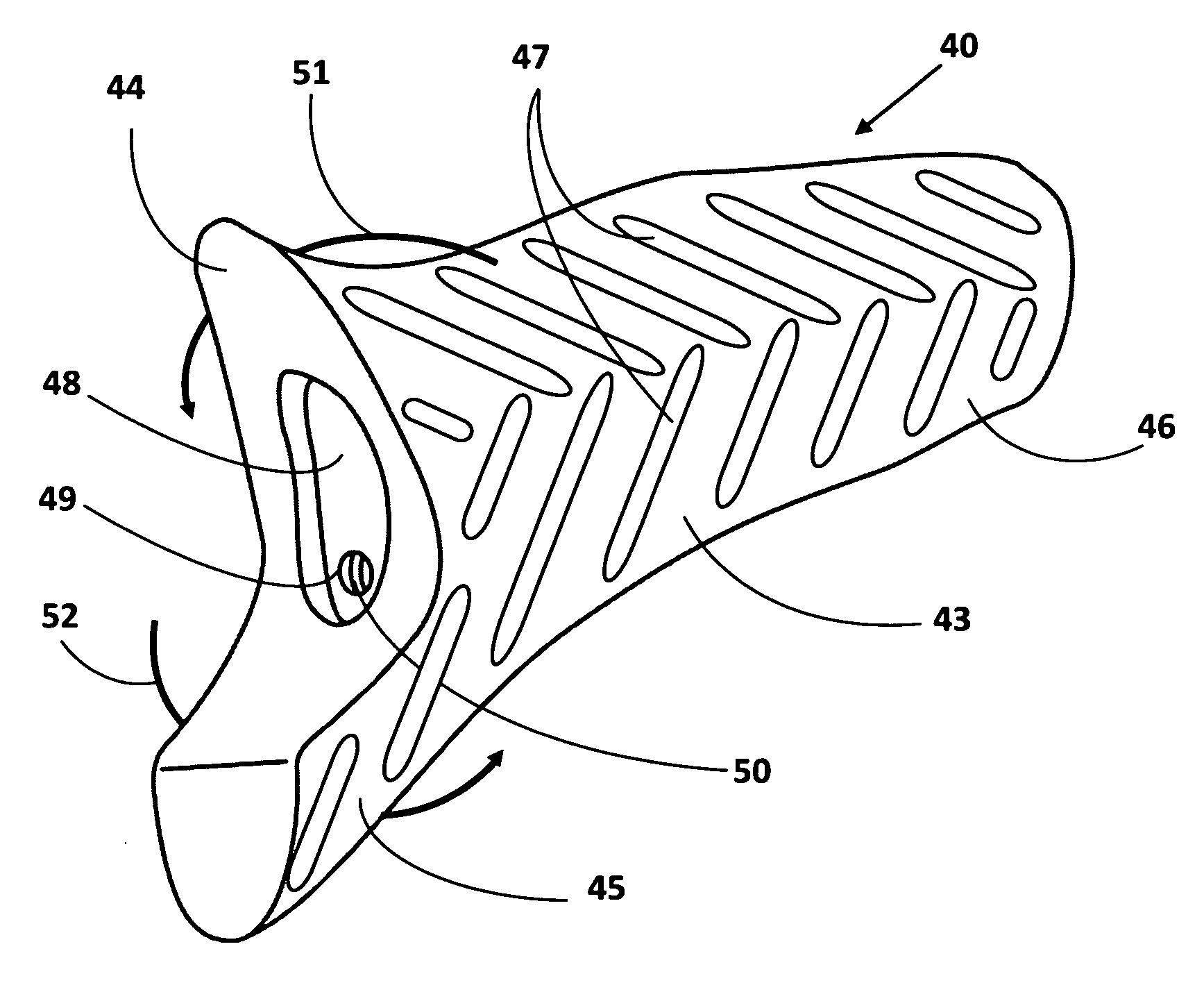
5) The prior art does not offer any blocking pegs to block the anterior, medial translation and internal,
medial rotation of the talus (ankle bone) on the calcaneus (heel bone) of the ankle-bone structure to obviate limitations in correcting abnormal foot
mechanics. The prior art can only minimize the excessive, abnormal motion. This often results in the failure of the prior-art implantation.
6) The prior art does not offer any blocking pegs to create
coupling-force affect to prevent superior and inferior togglings of the prior art within a sinus tarsi of a patient to eliminate the problem of displacement and failure of the prior art.
7) The prior art can not absorb the shocks caused by the body weight of a patient at every step the patient makes because the prior art does not offer any shaft or pegs, whose surfaces are modeled after the anatomically irregular surfaces of the talus (ankle bone), calcaneus (heel bone) of the ankle-bone structure of a patient to distribute the body weight of the patient over their entire anatomically irregular surfaces.

