

System and Method for Atmospheric Correction of Information
a technology of information correction and atmospheric science, applied in the field of atmospheric sciences, can solve the problems of degrading the remotely sensed image, altering the apparent spectral signature of the target being observed, and using and proving the assumption and the use of a single vertical representative path incorr
- Summary
- Abstract
- Description
- Claims
- Application Information
AI Technical Summary
Benefits of technology
Problems solved by technology
Method used
Image

Examples
Embodiment Construction
[0002]This invention was made with U.S. Government support under contract number FA8650-04-D-2413-D0006. The U.S. Government has certain rights in the invention.
BACKGROUND
[0003]The present invention relates to the field of atmospheric sciences, in particular, atmospheric correction in remote sensing.
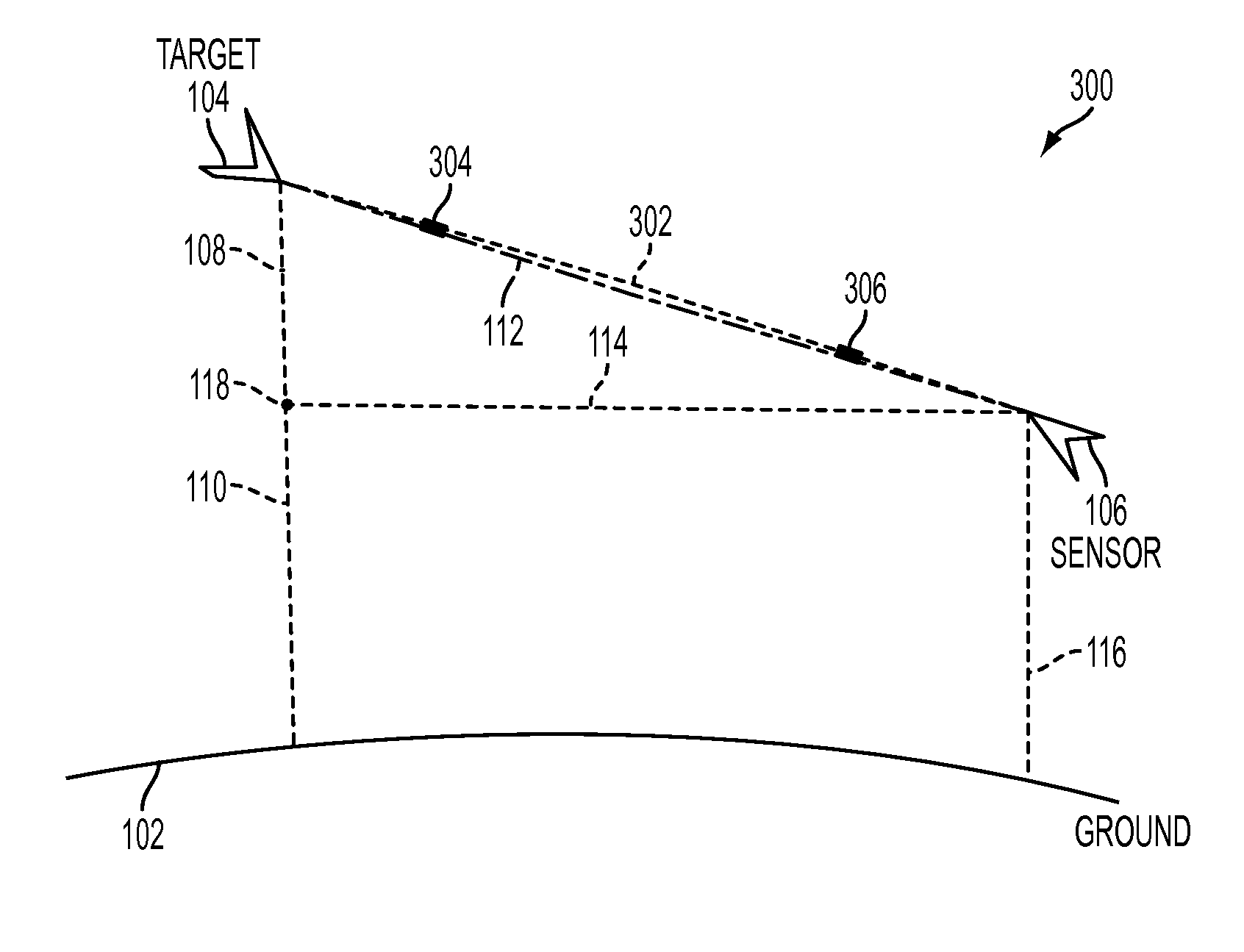
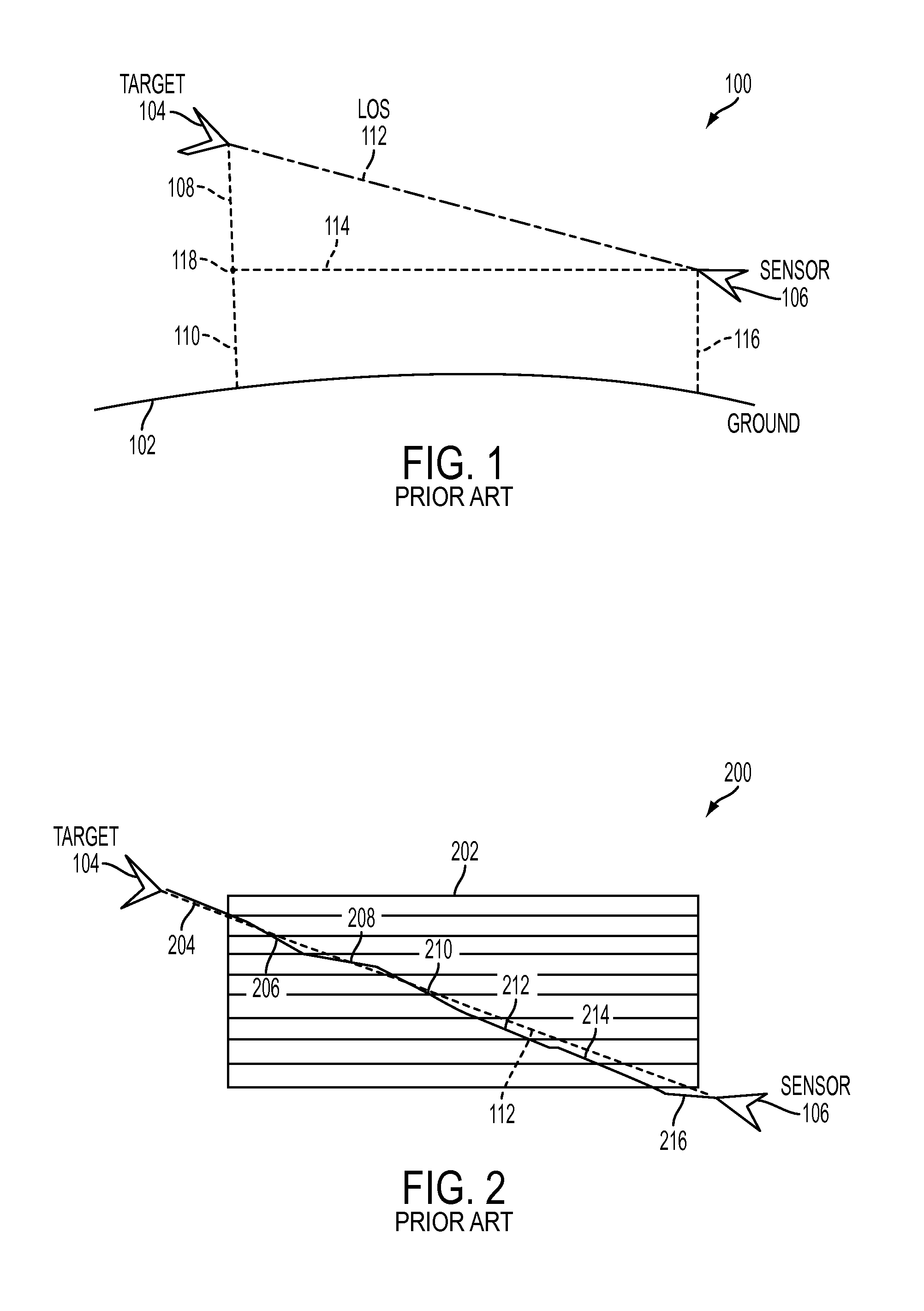
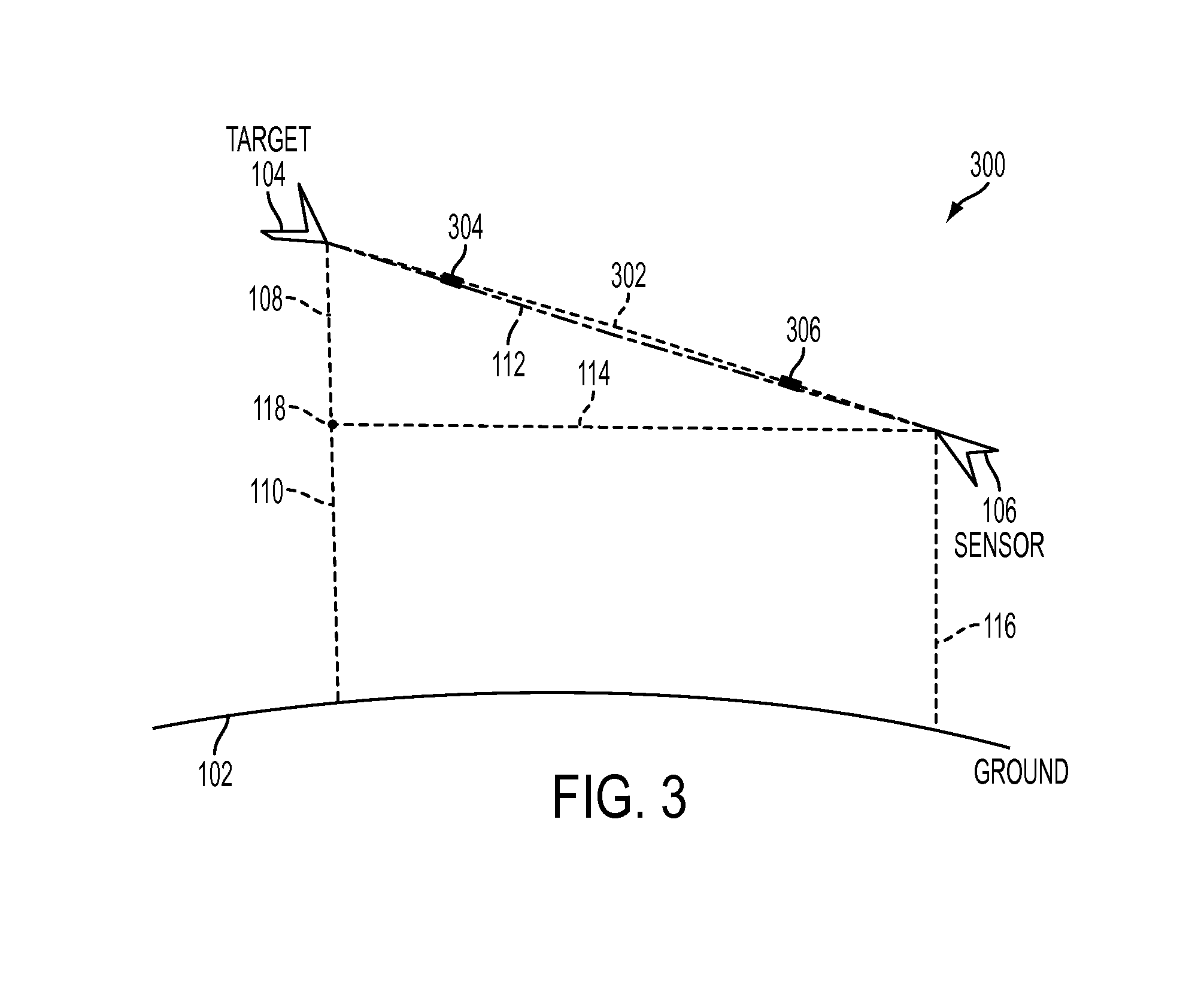
[0004]Remote sensing implies gathering information of an object or phenomenon using sensing devices that are not in direct contact with that object. An example is a sensing device or a sensor, which detects and measures the radiation from a target through an atmosphere to estimate the location and or spectral signature of the target. As a beam of radiation propagates through the atmosphere it undergoes wavelength dependent modification by the atmospheric constituents and elements that it encounters. The spectral characteristics of the beam change due to losses of energy to absorption, gains of energy by emission, and redistribution of energy by scattering and optical refraction. These at...
PUM
 Abstract
Description
Claims
Application Information