Panel, especially floor panel

a technology for floor panels and panels, applied in the field of floor panels, can solve the problems of not matching the tolerances of different components, and achieve the effect of increasing the stability of the connection and protecting the safety of overstretching

Active Publication Date: 2013-01-10
VÄLINGE INNOVATION AB
View PDF2 Cites 25 Cited by
  • Summary
  • Abstract
  • Description
  • Claims
  • Application Information

AI Technical Summary

Benefits of technology

[0009]This embodiment drastically simplifies production. There is no matching of tolerances of different components. Manufacture times and expenses are reduced, because it is not necessary to bring and keep together different components. Furthermore, it is ensured that the end consumer is not missing any components and unable to continue his work.
[0011]The tongue element is preferably exposed by means of a horizontal and a vertical slit. Not only does the width of the slits determine the strength of the link of the tongue element to the core material, but the choice of the width of the vertical slit also makes it possible to create a stop for the tongue element in the horizontal direction, so that the tongue element is safely protected against overstretching.
[0012]If a plurality of tongue elements spaced apart from one another is provided over the length of the lateral edge, the stability of the connection is increased because the free spring deflection in the longitudinal direction of the tongue element is limited. It is possible to select the distance between the individual tongue elements to be larger or smaller. The smaller the distance, the larger naturally the effective surface for locking, so that the transferable forces in the vertical direction are correspondingly high.
[0014]If the outer edge of the tongue element runs tilted at an angle to the top side, the joining motion is facilitated because with increasing motion the tongue element deflects deeper in the direction of the panel core.
[0018]If the hook elements are embodied such that there is a preload at the joint of two panels connected to one another, the lateral edges of the panels are pressed against one another with their vertical surfaces in the area of the top side, through which a tight connection on the top side of the plate can be achieved and the formation of gaps can be prevented.

Problems solved by technology

There is no matching of tolerances of different components.

Method used


Image

  • Panel, especially floor panel
  • Panel, especially floor panel
  • Panel, especially floor panel

Examples


Embodiment Construction

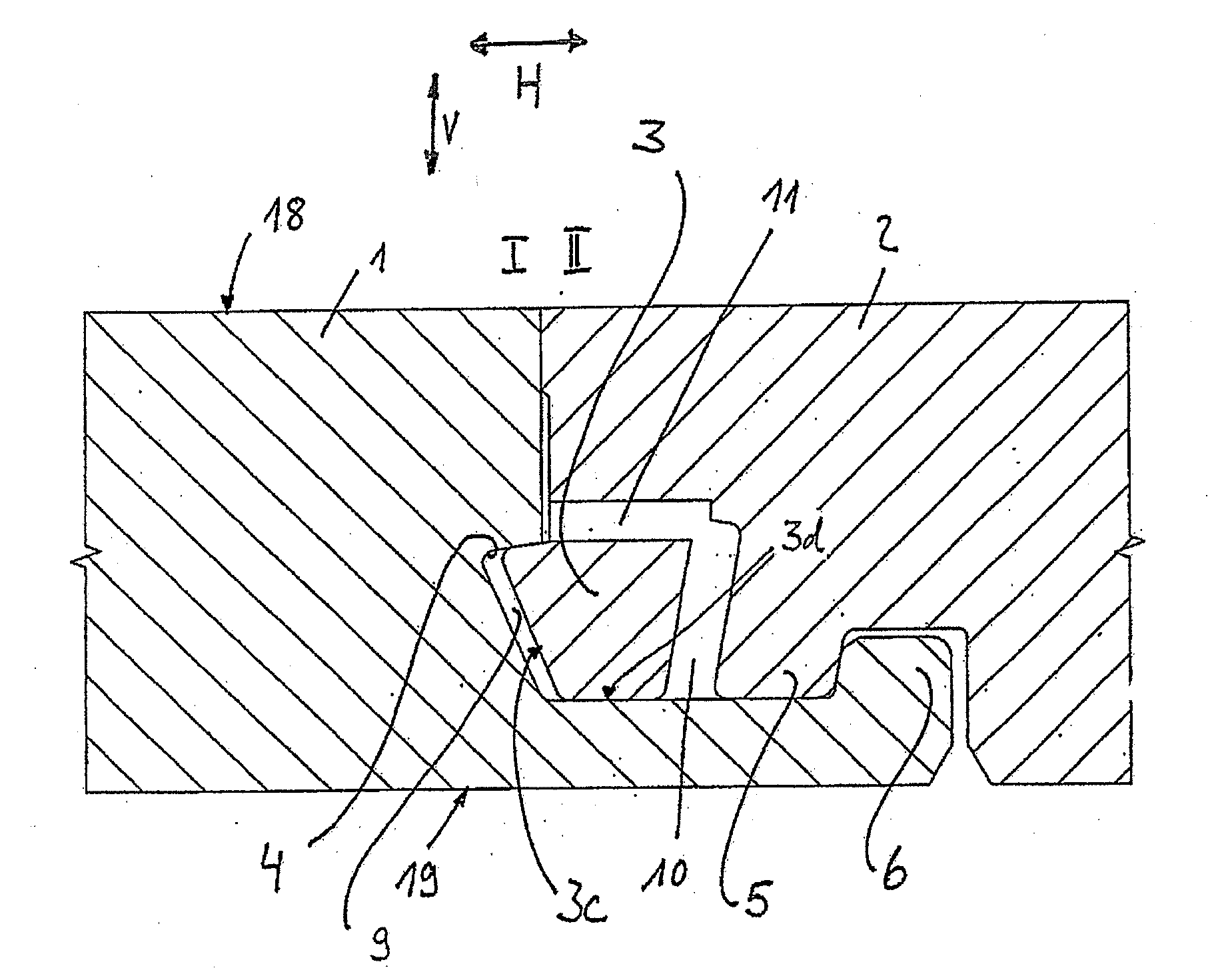
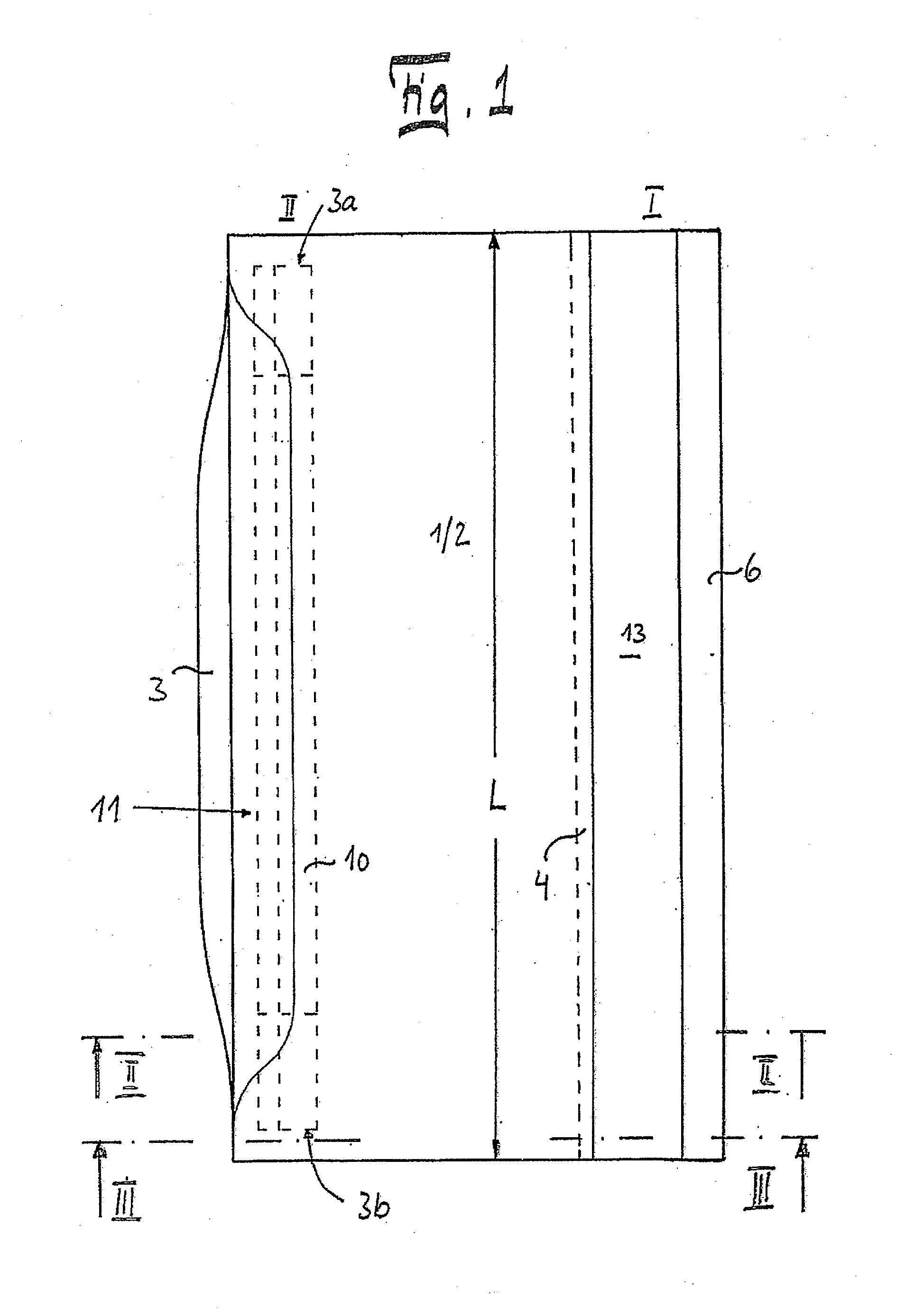
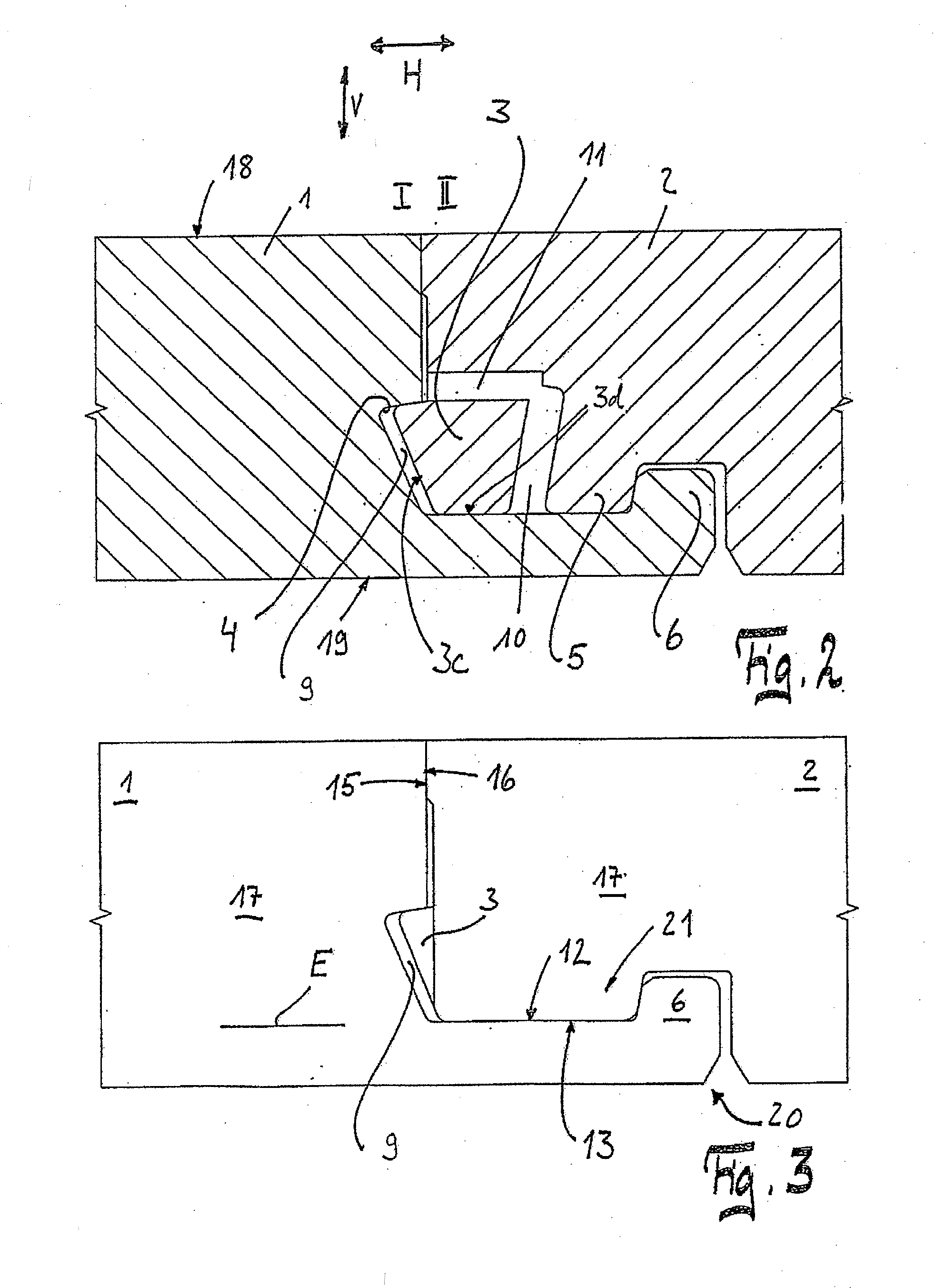
[0029]The panels 1, 2 are embodied identically. They comprise a core 17 of wood material or a wood material / plastic mixture. On their opposite lateral edges I, II the panels 1, 2 are profiled, the lateral edge I being milled from the top side 18 and the lateral edge II being milled from the bottom side 19. The tongue element 3 is embodied on the lateral edge II, which element was produced by cutting free the core 17 in that a horizontal slit 11 and a slit 10 running essentially vertically were milled. The lateral edges I, II have the length L. In the longitudinal direction of the lateral edge II, the tongue element 3 is connected on its ends 3a, 3b to the core material. The exposure of the tongue element 3 from the core 17 occurs through the slits 10, 11 only. The outer edge 3c of the tongue element 3 is tilted at the angle .alpha. with respect to the top side 18 of the panel 2. The vertical surfaces of the lateral edges I, II are machined such that mating surfaces 15, 16 form in th...


PUM


Abstract

A panel, in particular floor panel, with a core of wood material or a wood material / plastic mixture, a top side and a bottom side, which panel has on at least two opposite lateral edges a profiling corresponding to one another such that two identically embodied panels can be connected and locked to one another by an essentially vertical joining motion in the horizontal and vertical directions, wherein the locking in the vertical direction can be brought about by at least one tongue element movable in the horizontal direction, which element snaps into place during the joining motion behind a locking edge extending essentially in the horizontal direction, is characterized in that the tongue element is formed in one piece out of the core.

Description

CROSS REFERENCE TO RELATED APPLICATIONS[0001]The present application is a continuing application of co pending U.S. application Ser No. 12 / 282,838, filed on Jan. 21, 2009, the contents of which are incorporated by reference herein in its entirety.FIELD OF THE INVENTION[0002]The invention relates to a panel, in particular a floor panel, with a core made of wood material or a wood material / plastic mixture, a top side and a bottom side, which panel has on at least two opposite lateral edges a profiling corresponding to one another such that two identically embodied panels can be connected and locked to one another by an essentially vertical joining motion in the horizontal and vertical directions, wherein the locking in the vertical direction can be brought about by at least one tongue element movable in the horizontal direction, which element snaps into place during the joining motion behind a locking edge extending essentially in the horizontal direction.BACKGROUND OF INVENTION[0003]...

Claims


Application Information

Patent Timeline
Patent Type & Authority Applications(United States)
IPC IPC(8): E04B5/00
CPCE04F15/02E04F15/02038E04F15/04Y10T428/167E04F2201/0146E04F2201/041F16B5/0076E04F2201/0138
Inventor BRAUN, ROGERGROEKE, CARSTEN
Owner VÄLINGE INNOVATION AB
Why Eureka
Try Eureka