Power source switch device and power source system provided with same

a technology of power source switch and power source system, which is applied in the direction of motor/generator/converter stopper, ignition automatic control, dynamo-electric converter control, etc., can solve problems such as adversely affecting other devices, and achieve the effect of reducing scal

Inactive Publication Date: 2013-01-10
PANASONIC CORP
View PDF4 Cites 13 Cited by
  • Summary
  • Abstract
  • Description
  • Claims
  • Application Information

AI Technical Summary

Benefits of technology

[0013]The power switching device and the like of the present disclosure allow for a reduction in scale.

Problems solved by technology

Such inrush current may damage elements along the electric circuit between the power supply and the capacitance element, or may adversely affect other devices due to a temporary lowering in the power supply voltage.

Method used


Image

  • Power source switch device and power source system provided with same
  • Power source switch device and power source system provided with same
  • Power source switch device and power source system provided with same

Examples


embodiment 1

[0054]Structure

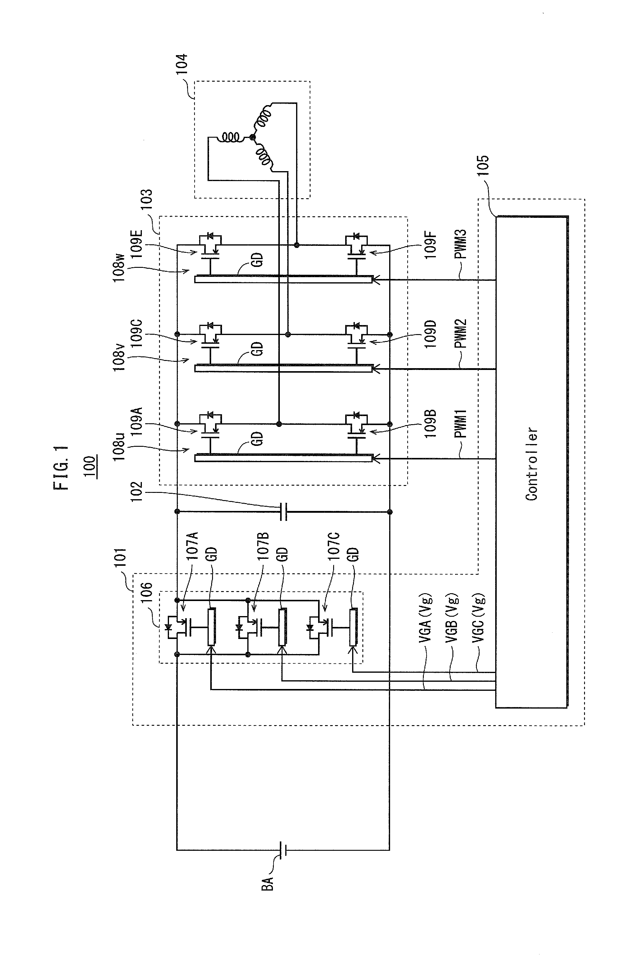
[0055]FIG. 1 illustrates the overall configuration of a power system 100 provided with a power switching device according to Embodiment 1.

[0056]The power system 100 is connected to a DC power supply BA at the input side and to a motor 104 at the output side. The power system 100 is provided with a power switching device 101, a smoothing capacitor 102, and an inverter 103.

[0057]The DC power supply BA is either a DC power supply obtained by rectifying power from a power supply system, or a battery-type DC power supply (typically a nickel-metal hydride, lithium-ion, etc. secondary battery).

[0058]The motor 104 is a three-phase motor composed of three-phase coils that receive a supply of three-phase power.

[0059]The power switching device 101 opens and closes an electric circuit connecting the DC power supply BA and the smoothing capacitor 102 in response to commands. The power switching device 101 includes a controller 105 and a current amount variation unit 106.

[0060]The ...

embodiment 2

[0108]In Embodiment 1, the semiconductor element through which current flows during the first period is fixed as the semiconductor element 107A (FIG. 4). In the present embodiment, a structure is to switch the semiconductor element through which current flows during the first period so as to disperse the burden on the semiconductor elements.

[0109]Structure

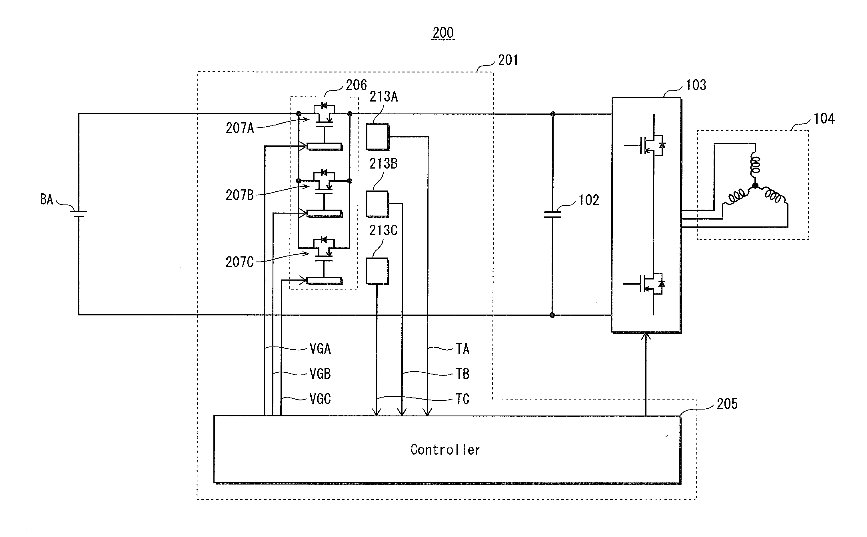
[0110]FIG. 5 illustrates the overall configuration of a power system 200 provided with a power switching device according to Embodiment 2. In addition to the structure of the power switching device 101 (see Embodiment 1 and FIG. 1), a power switching device 201 is provided with temperature detection circuits 213A, 213B, and 213C. Below, structural components that are the same as in Embodiment 1 are provided with the same reference signs, and a description thereof is omitted.

[0111]A current amount variation unit 206 includes semiconductor elements 207A, 207B, and 207C having a similar structure as in Embodiment 1.

[0112]The temperatu...

modification to embodiment 2

[0121]In Embodiment 2, the temperature of the semiconductor elements is detected individually. Alternatively, a structure may be adopted to detect the overall temperature of the semiconductor elements (the temperature of the current amount variation unit 206).

[0122]Structure

[0123]FIG. 7 illustrates the overall configuration of a power system 200a provided with a power switching device according to the present modification. In addition to the structure of the power switching device 101 (see Embodiment 1 and FIG. 1), a power switching device 201a is provided with a temperature detection circuit 213a. The following explanation focuses on the differences from the power switching device 201 of Embodiment 2.

[0124]The temperature detection circuit 213a detects the overall temperature Tsur in ° C. of the semiconductor elements 207A, 207B, and 207C.

[0125]The controller 205a acquires information on the temperature Tsur detected by the temperature detection circuit 213a and, in accordance with...


PUM


Abstract

Provided are semiconductor elements 107A, 107B, and 107C that allow a current to flow that is at most a maximum current determined by the level of control signals VGA, VGB, and VGC and that depends on the difference between the voltage of a DC power supply BA and the charging voltage of a capacitor 102, a controller 105 that outputs a control signal to each semiconductor element, and a temperature detection circuit that detects the temperature of each semiconductor element. Until a predetermined time elapses after the electric circuit is closed, the controller 105 adjusts the level of each control signal based on the temperature detected by the temperature detection circuit so that current through the electric circuit does not exceed a current limit, and after the predetermined time period elapses, the controller 105 adjusts the level of each control signal so that current through the electric circuit is allowed to exceed the current limit.

Description

TECHNICAL FIELD[0001]The present invention relates to a power switching device that uses a precharging method to switch an electric circuit connecting a DC power supply and a capacitor, and to a power system provided with the power switching device.BACKGROUND ART [0002]A power system that supplies power from a battery or other DC power supply to a load, such as a motor, is mainly constituted by a capacitance element, a power switching device, and a power converter. The capacitance element is a smoothing capacitor or the like. The power switching device switches an electric circuit connecting the DC power supply and the capacitance element in response to commands. The power convertor converts DC power to AC power.[0003]While not driving the load, the power switching device leaves the electric circuit connecting the DC power supply and the capacitance element in an open state (i.e. cuts off the electric circuit). Conversely, when driving the load, the power switching device places the...

Claims


Application Information

Patent Timeline
Patent Type & Authority Applications(United States)
IPC IPC(8): G05B24/02
CPCH02M2001/327B60L3/00B60L2270/20B60L2240/525B60L3/003H02M1/327
Inventor TAGOME, MASAKI
Owner PANASONIC CORP
Why Eureka
Try Eureka