Eddy current measuring sensor and inspection method using this eddy current measuring sensor

a technology of eddy current measuring sensor and eddy current measurement, which is applied in the direction of magnetic property measurement, material magnetic variables, instruments, etc., can solve the problems of limited application range of this technology, difficult 100% inspection in a line, and increase in material costs, so as to reduce the effect of an edge effect and high detection accuracy

Inactive Publication Date: 2013-01-10
TOYOTA JIDOSHA KK
View PDF2 Cites 18 Cited by
  • Summary
  • Abstract
  • Description
  • Claims
  • Application Information

AI Technical Summary

Benefits of technology

[0021]The invention makes it possible to carry out a hardening depth / hardness measurement test with high detection accuracy by a strong magnetic field of a probe coil even when inspecting an induction-hardened component having an outer diameter that changes significantly, and reduce an edge effect by appropriately controlling the spread and direction and the like of the magnetic field.

Problems solved by technology

However, with this destructive inspection method, the steel used as the sample is discarded, which leads to an increase in material costs.
Also, in addition to the inspections taking longer, 100% inspection in a line is difficult, so steel may end up being moved to the next process without defects that occur sporadically being detected.
Also, the steel that is the object being inspected needs to be inserted through the encircling coil, so the range of application of this technology is limited to shaft components with a substantially constant outer diameter.
That is, the inspection is difficult to carry out on a component in which the outer diameter changes significantly, such as a crankshaft, for example.
However, the probe coil has a weaker magnetic field and the distance to the steel must be precisely controlled, so while it is suitable for flaw detection testing and foreign material discrimination testing, it is difficult to use for hardening depth / hardness measurement testing.
Further, with the probe coil according to the related art, the magnetic field in the work is unable to be widened or offset to one side, so it is difficult to appropriately control the spread and direction and the like of the magnetic field.
Furthermore, in flaw detection testing with the probe coil as well, a so-called edge effect in which a flaw signal ends up getting buried in an edge signal at an end portion of the steel severely limits the inspectable range and the parts that can be inspected and the like, so the reduction of this edge effect in eddy current measurements using a probe coil has become an issue.

Method used


Image

  • Eddy current measuring sensor and inspection method using this eddy current measuring sensor
  • Eddy current measuring sensor and inspection method using this eddy current measuring sensor
  • Eddy current measuring sensor and inspection method using this eddy current measuring sensor

Examples


first embodiment

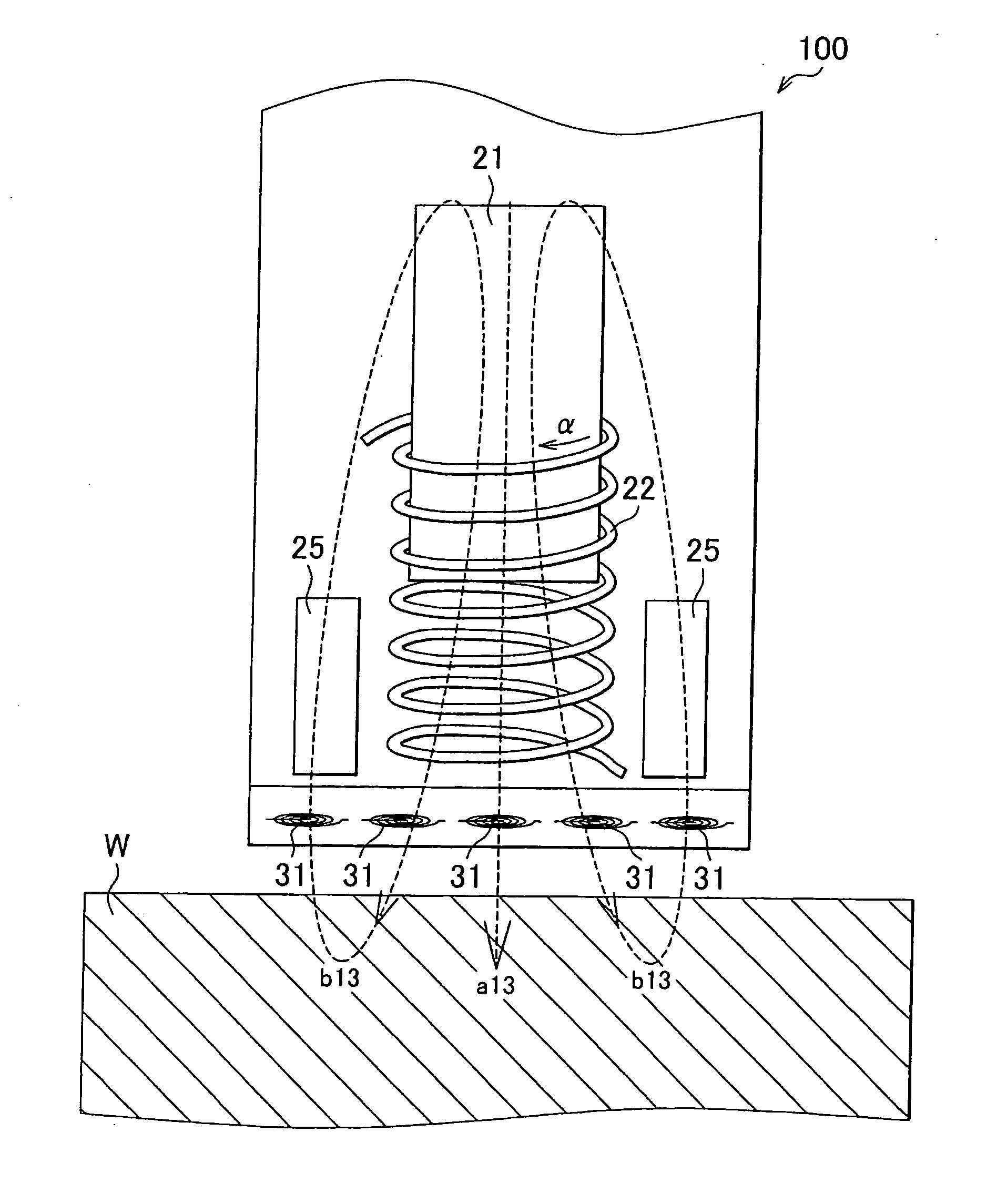
[0053]First, an eddy current measuring sensor 100 according to the invention will be described with reference to FIGS. 4 to 10. Incidentally, in this specification, the upper side in FIG. 4 will be referred to as up, the lower side in FIG. 4 will be referred to as down, the right side in FIG. 4 will be referred to as the right, and the left side in FIG. 4 will be referred to as the left. Moreover, the side toward the surface of the paper on which FIG. 4 is drawn will be referred to as the front, and the side away from the surface in the depth direction of the paper on which FIG. 4 is drawn will be referred to as the back. Also, to simplify the description, in FIGS. 4 and 6 to 10, only the sub-cores 25 on the left and right ends are shown; all of the other sub-cores 25 are omitted.

[0054]As shown in FIGS. 4 and 5, the eddy current measuring probe sensor 100 according to this embodiment has an exciting portion 20 and a detecting portion 30. The exciting portion 20 applies a predetermin...

second embodiment

[0079]Next, an eddy current measuring sensor 200 according to the invention will be described with reference to FIGS. 11 to 15. Incidentally, portions in the description of the eddy current measuring sensor in the embodiment described below that are common to portions in the embodiment described above will be denoted by like reference characters and descriptions of those portions will be omitted. Also, to simplify the description, in FIGS. 11, 13, and 14, only the sub-cores 25 and sub-coils 26 on the left and right ends are shown; all of the other sub-cores 25 and sub-coils 26 are omitted.

[0080]As shown in FIGS. 11 and 12, the eddy current measuring probe sensor 200 according to this embodiment has an exciting portion 220 and a detecting portion 230, similar to the first embodiment described above. The exciting portion 220 applies a predetermined AC excitation signal to a work W that is the component to be measured, and the detecting portion 230 detects a detection signal by an eddy...

third embodiment

[0101]Next, an eddy current measuring sensor according to the invention will be described with reference to FIGS. 16 to 19. Incidentally, to simplify the description, in FIGS. 16 and 18 to 19A only the sub-cores 25 and the sub-coils 26 on the left and right ends are shown; all of the other sub-cores 25 and sub-coils 26 are omitted.

[0102]As shown in FIG. 16, an eddy current measuring probe sensor 300 according to this embodiment has a plurality of detection coils 31 of which the detecting portions are arranged radially about an axial portion of a primary exciting portion, similar to the second embodiment described above. The detection coils 31 in this embodiment are formed of pancake coils, just as in the embodiment described above, but they may also be formed of solenoid coils that are wound around inside the main coil 22 and the sub-coils 26, for example.

[0103]Moreover, the detection coils 31 are each configured so as to be able to independently and selectively make a detection sig...


PUM


Abstract

An eddy current measuring probe sensor has an exciting portion and a detecting portion. The exciting portion includes a primary exciting portion that includes a main core formed of a cylindrical magnetic body and a main coil that is a solenoid coil wound in a circumferential direction around the main core, and a plurality of secondary exciting portions that include sub-cores formed of cylindrical magnetic bodies that are arranged around the primary exciting portion in a manner such that an axial direction of each of the sub-cores is the same as an axial direction of the main core. The plurality of secondary exciting portions are configured to be able to change the position of each sub-core independently in the axial direction relative to the primary exciting portion

Description

BACKGROUND OF THE INVENTION[0001]1. Field of the Invention[0002]The invention relates to an eddy current measuring sensor and an inspection method using this eddy current measuring sensor. More particularly, the invention relates to an eddy current measuring sensor that improves the inspection accuracy in eddy current inspection, and an inspection method using this eddy current measuring sensor.[0003]2. Description of the Related Art[0004]Steel that has been induction hardened (hereinafter simply referred to as “steel”), in which metal (conductive material) is hardened by high-frequency induction heating, is used for mechanical parts such as underbody parts and engine parts of tomobiles and motorcycles. With regards to the hardened layer depth of surface hardening (hereinafter also referred to as the “hardening depth”) and the hardness in the induction hardening of steel, the effective hardened layer depth and the total hardened layer depth are standardized. Therefore, it is necessa...

Claims


Application Information

Patent Timeline
Patent Type & Authority Applications(United States)
IPC IPC(8): G01R33/12
CPCG01N27/9046G01N27/90
Inventor YAMAMOTO, TAKANARI
Owner TOYOTA JIDOSHA KK
Why Eureka
Try Eureka