Control Circuitry And Method For Controlling A Bi-Directional Switch System, A Bi-Directional Switch, A Switching Matrix And A Medical Stimulator

Active Publication Date: 2013-01-10
MEDTRONIC BAKKEN RES CENT
View PDF2 Cites 31 Cited by
  • Summary
  • Abstract
  • Description
  • Claims
  • Application Information

AI Technical Summary

Benefits of technology

[0048]The method according to the fifth aspect of the invention provides the same benefits as the control circuitry according to the first aspect of the invention and has similar embodiments with similar effects as the corresponding embodiments of the circuitry.

Problems solved by technology

However, when the energy storage element is being charged, the voltages of the terminals of the energy storage element become connected to fixed voltage levels, which may prevent the control circuit of generating a control voltage which may reliably switch the bi-directional switch on or off.

Method used


Image

  • Control Circuitry And Method For Controlling A Bi-Directional Switch System, A Bi-Directional Switch, A Switching Matrix And A Medical Stimulator
  • Control Circuitry And Method For Controlling A Bi-Directional Switch System, A Bi-Directional Switch, A Switching Matrix And A Medical Stimulator
  • Control Circuitry And Method For Controlling A Bi-Directional Switch System, A Bi-Directional Switch, A Switching Matrix And A Medical Stimulator

Examples


first embodiment

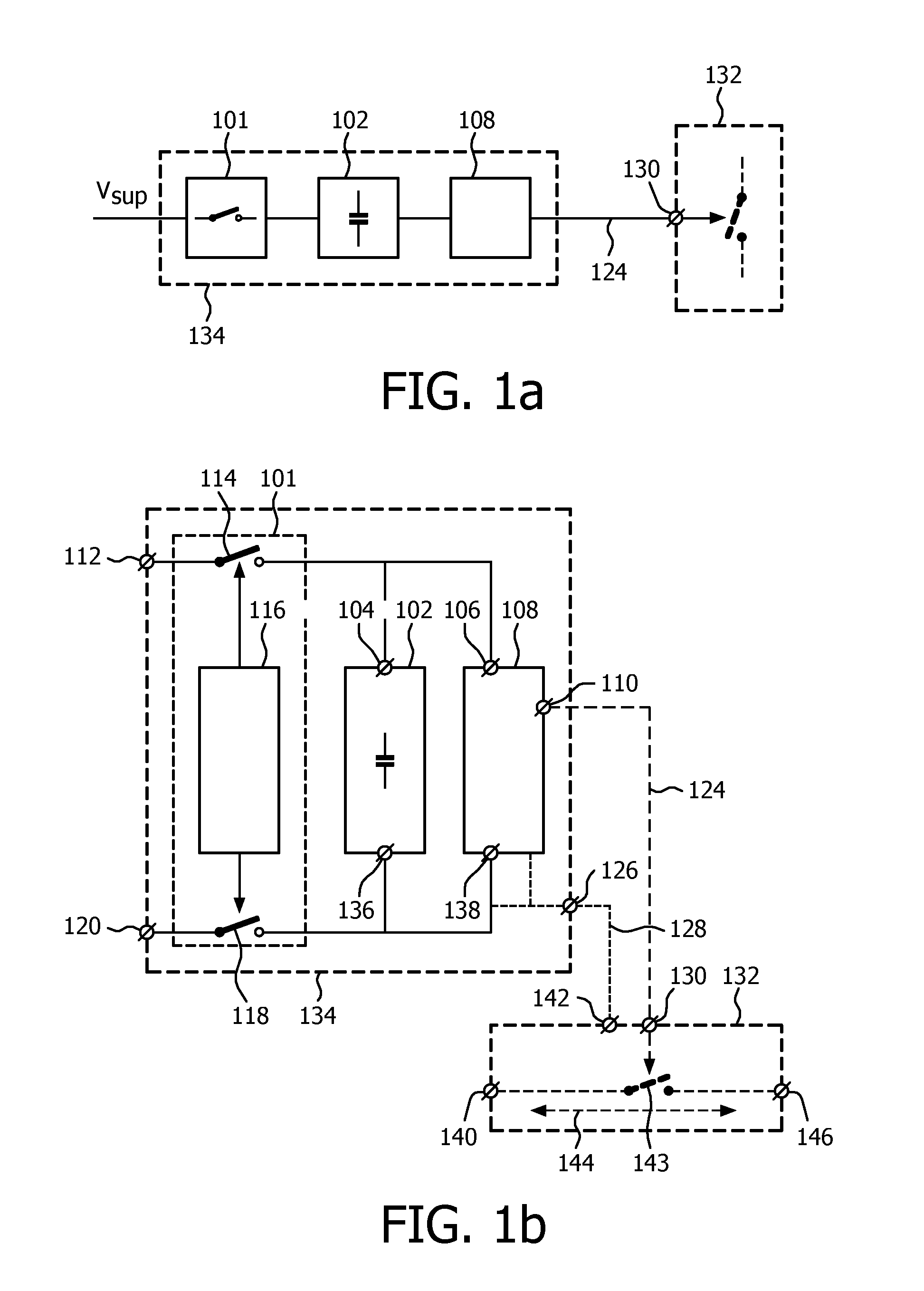
[0077]A first embodiment is shown in FIG. 1a. A control circuitry 134 for controlling a bi-directional switch 132 is shown. The bi-directional switch 132 comprises a control terminal 130 to receive a control voltage 124 to control an on state and an off state of the bi-directional switch 132. The control circuitry 134 comprises an energy storage element 102, a coupling means 101 and a control circuit 108. The coupling means 101 couples the energy storage element 102 to a supply voltage Vsup to charge the energy storage element 102. The coupling means 101 only couples the energy storage element 102 to the supply voltage Vsup when the bi-directional switch 132 is in the off state. The control circuit 108 receives power from the energy storage element 102 and supplies the control voltage 124 which has a voltage level that is independent of the supply voltage Vsup when the energy storage element 102 is not coupled to the supply voltage Vsup.

[0078]Another embodiment is shown in Fig. lb. ...

embodiment 202

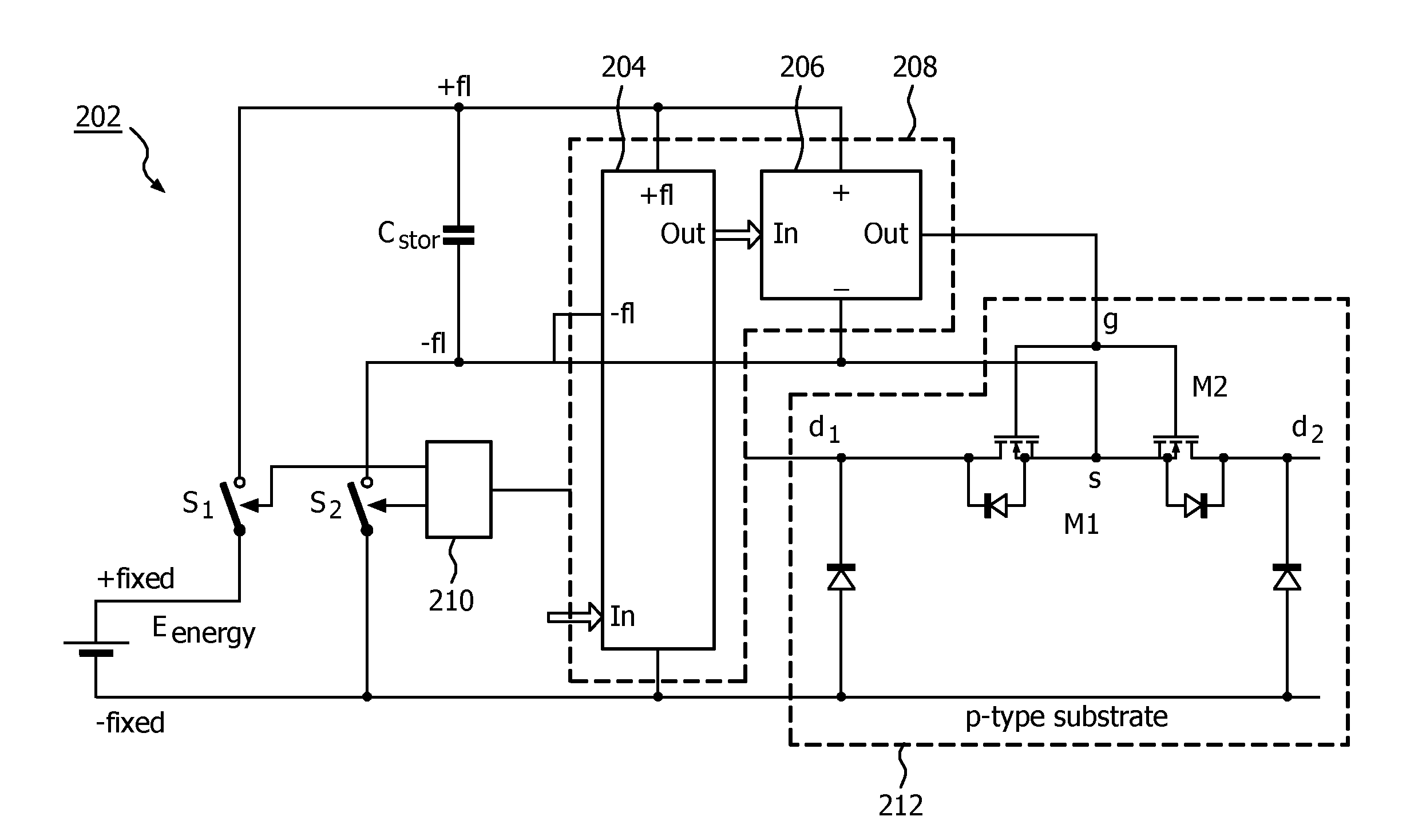
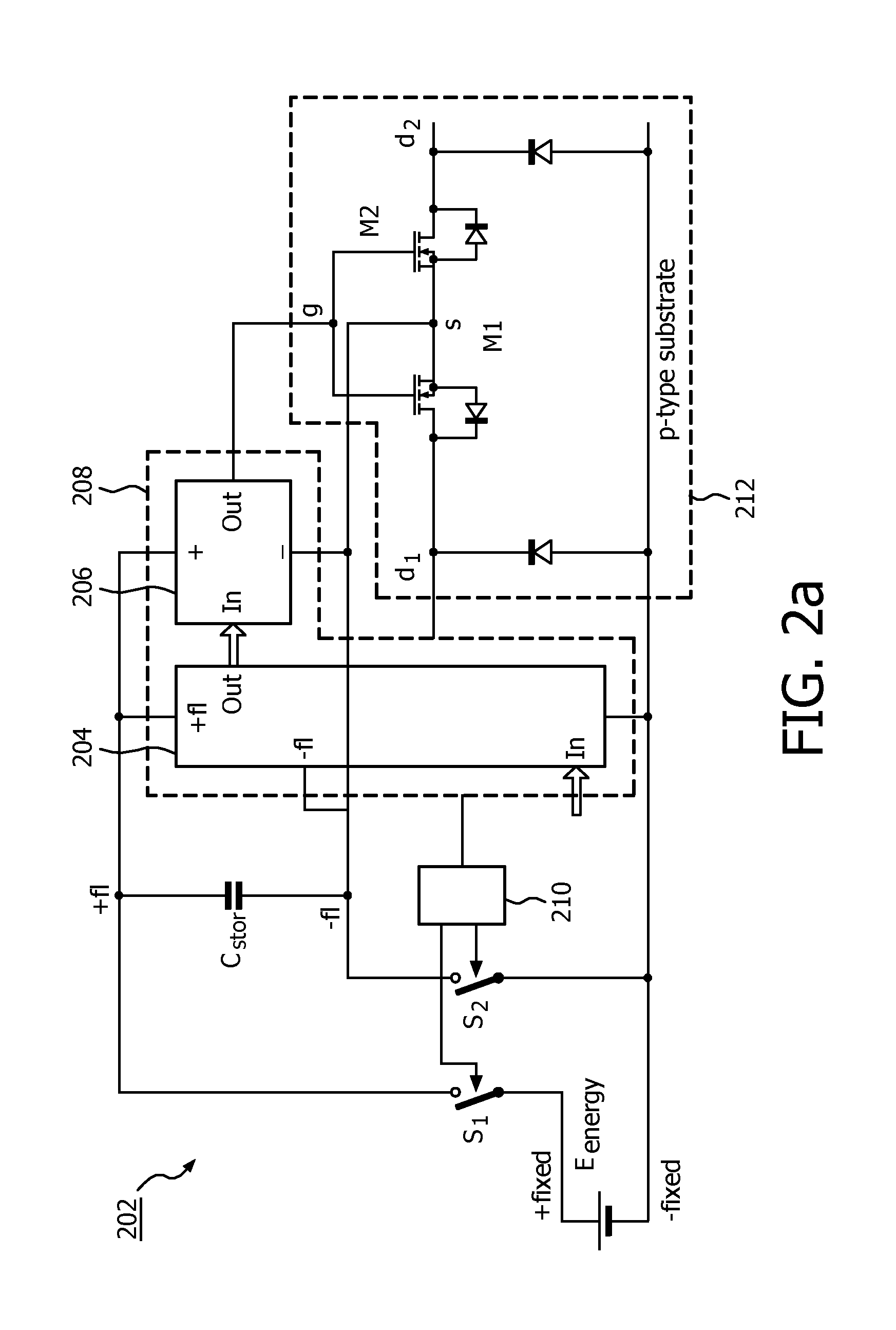
[0086]FIG. 2a schematically shows an embodiment 202 of a control circuitry and a bi-directional switch 212 which may be manufactured in p-type substrate semiconductor technology. The bi-directional switch 212 is implemented with two NMOS transistors M1, M2 which are placed in an anti-series configuration, which means that they have a common gate g and a common source s. A drain d1 of one of the MOS transistors M1, M2 is a first I / O terminal of the bi-directional switch 212 and a drain d2 of the other one of the MOS transistors M1, M2 is a second I / O terminal of the bi-directional switch 212.

[0087]The control circuitry comprises a first switch S1, a second switch S2, a storage capacitor Cstor, a first controller 210 and a second controller 208. A voltage supply Eenergy provides a first voltage +fixed and a second voltage −fixed which is lower than the first voltage +fixed. The first switch Si receives the first voltage +fixed and provides, when the first switch S1 is closed, the firs...


PUM


Abstract

A control circuitry (134) and a method for controlling a bi-directional switch (132) is provided. The bi-directional switch (132) having a control terminal (130) for receiving a control voltage (124) to control an on state and an off state of the bi-directional switch (132) and at least one semiconductor switch in a bi-directional main current path. The control circuitry (134) comprises an energy storage element (102), a coupling means (101) to couple the energy storage element (102) to a supply voltage to charge the energy storage element (102), and a control circuit (108) configured to receive power from the energy storage element (102) and configured to supply the control voltage having a voltage level being independent of the supply voltage when the energy storage element (102) is not coupled to the supply voltage. The coupling means (101) is configured for only coupling the 132 energy storage element (102) to the supply voltage when the bi-directional switch (132) is in the off state.

Description

FIELD OF THE INVENTION[0001]The invention relates to the field of control circuitry for bidirectional switches.BACKGROUND OF THE INVENTION[0002]In the area of medical stimulators, there is a trend towards an increased number of stimulation electrode sites to improve therapeutic efficacy by accurate stimulation of the intended target volume using field steering. Besides stimulation, there is an increased demand for accurate sensing of neural activity. Both trends require the presence of a relatively large cross-point switch matrix to couple stimulation and / or sensing electronics to selected probe electrode sites. The available volume for energy storage is decreasing in the state-of-the-art medical stimulators, although the required energy for brain stimulation is substantially constant. Consequently, there is less room for a battery, and, thus, the circuitry of the medical stimulator has to be a low power circuitry. The high number of switches of a cross-point switch matrix imposes a...

Claims


Application Information

Patent Timeline
Patent Type & Authority Applications(United States)
IPC IPC(8): H03K17/66
CPCA61N1/36185H03K17/687H03K17/063A61N1/05H03K17/06H03K17/66H02J7/00H02J7/345
Inventor BLANKEN, PIETER GERRITTOL, JEROEN JACOB ARNOLDSCHOOFS, FRANCISCUS ADRIANUS CORNELIS MARIAVAN GOOR, DAVE WILLEM
Owner MEDTRONIC BAKKEN RES CENT
Why Eureka
Try Eureka