
Spectral Purity Filters for Use in a Lithographic Apparatus

a lithographic apparatus and filter technology, applied in the field of spectral purity filters, can solve the problems of undesirable ‘out-of-band’ radiation, deterioration of image quality of resist patterns, and not only emitted desired ‘in-band’ euv radiation, so as to inhibit degradation or environmental damage, promote reflection of at least a portion

Inactive Publication Date: 2013-01-10
ASML NETHERLANDS BV
View PDF2 Cites 2 Cited by
  • Summary
  • Abstract
  • Description
  • Claims
  • Application Information

AI Technical Summary

Benefits of technology

[0016]The coating may be arranged to absorb at least a portion of the first wavelength of radiation. The coating may be arranged to inhibit reflection of at least a portion of the first wavelength of radiation. The coating may be arranged to promote reflection of at least a portion of the second wavelength. The coating may be arranged to inhibit degradation or environmental damage to the aperture.

Problems solved by technology

Practical EUV Sources, such those which generate EUV radiation using a plasma, do not only emit desired ‘in-band’ EUV radiation, but also undesirable ‘out-of-band’ radiation.
One reason is that resist is sensitive to out-of-band wavelengths of radiation, and thus the image quality of patterns applied to the resist may be deteriorated if the resist is exposed to such out-of-band radiation.
Furthermore, out-of-band infrared radiation, for example the 10.6 μm radiation in some laser produced plasma sources, leads to unwanted and unnecessary heating of the patterning device, substrate and optics within the lithographic apparatus.
Such heating may lead to damage of these elements, degradation in their lifetime, and / or defects or distortions in patterns projected onto and applied to a resist-coated substrate.
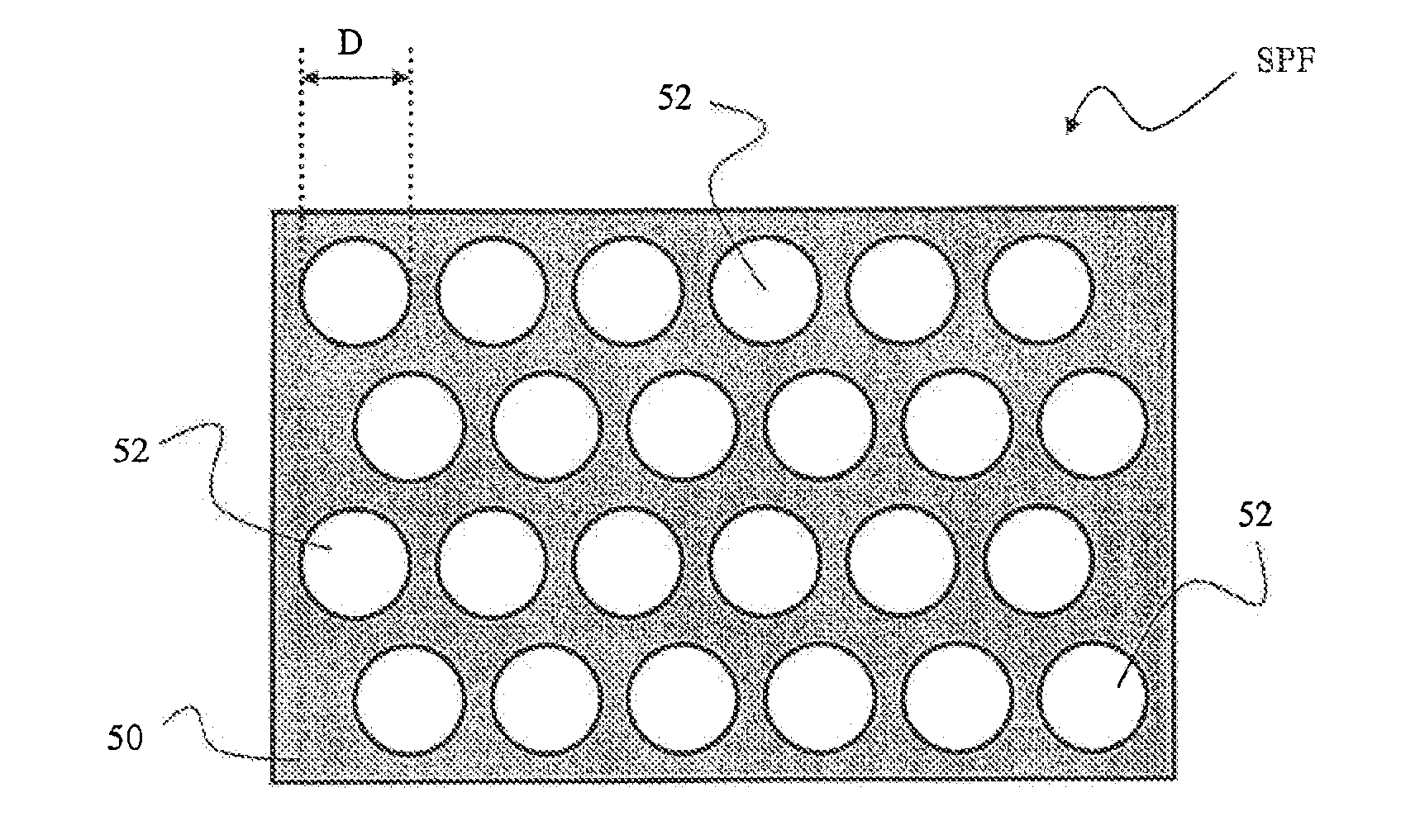
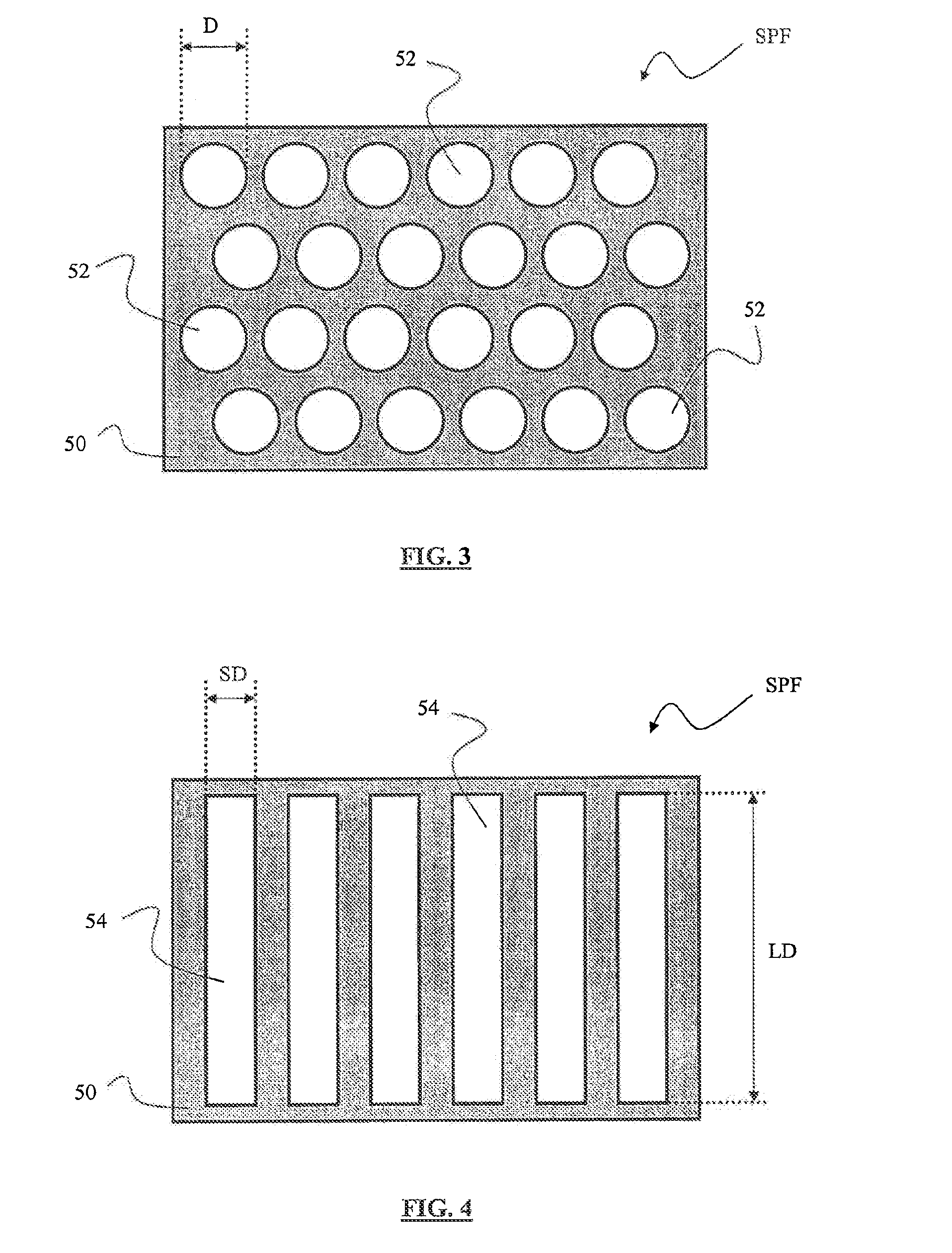
One problem associated with spectral purity filters provided with apertures is that the apertures are so small that the manufacturing options that are available to create the apertures are limited and / or expensive.
Furthermore, the small diameter of the apertures reduces the mechanical robustness of the spectral purity filter.

Method used


Image

  • Spectral Purity Filters for Use in a Lithographic Apparatus
  • Spectral Purity Filters for Use in a Lithographic Apparatus
  • Spectral Purity Filters for Use in a Lithographic Apparatus

Examples


Embodiment Construction

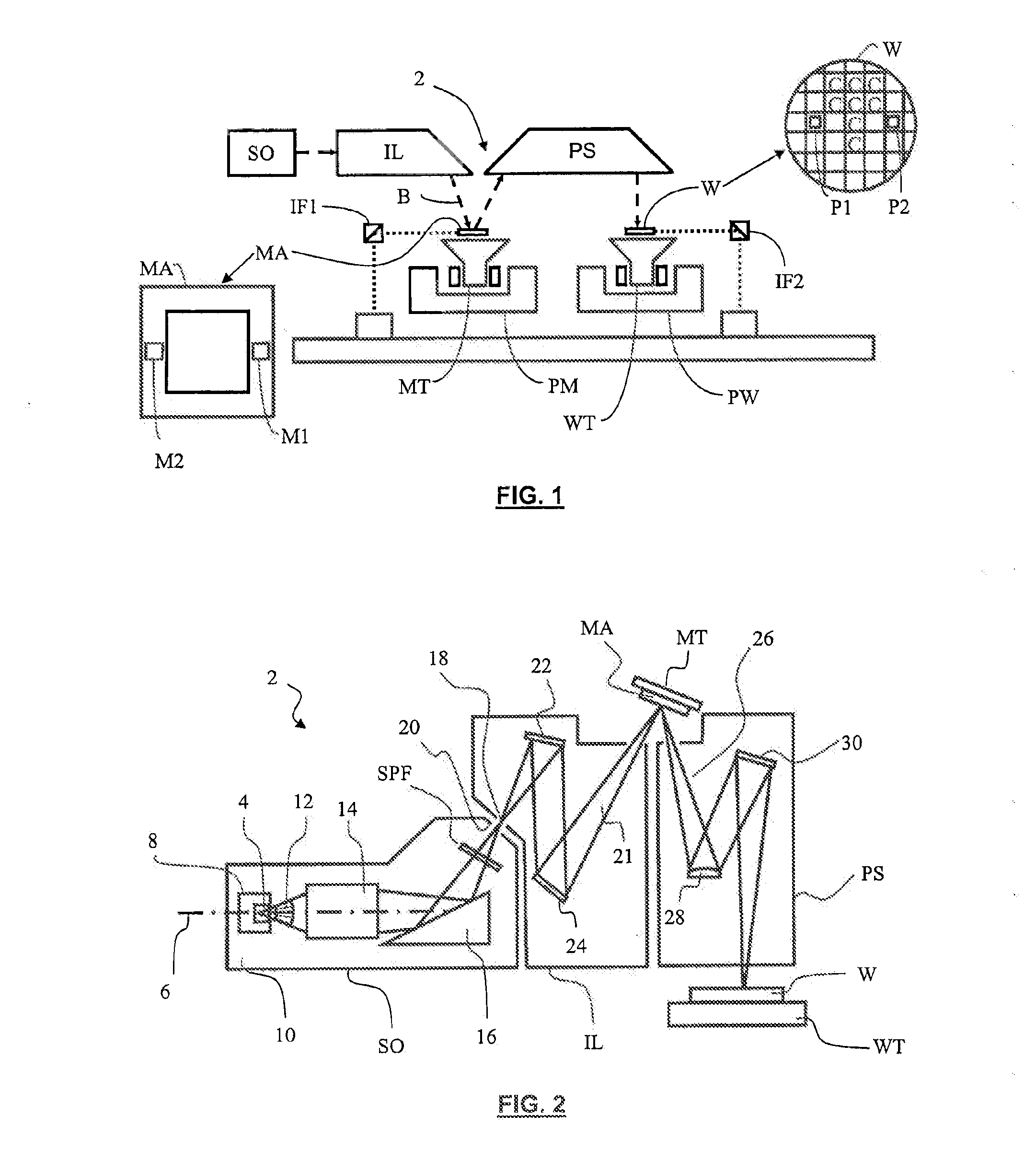
[0057]FIG. 1 schematically depicts a lithographic apparatus 2 according to one embodiment of the invention. The apparatus 2 includes: an illumination system (illuminator) IL configured to condition a radiation beam B (e.g., EUV radiation); a support structure (e.g., a mask table) MT constructed to support a patterning device (e.g., a mask) MA and connected to a first positioner PM configured to accurately position the patterning device in accordance with certain parameters; a substrate table (e.g., a wafer table) WT constructed to hold a substrate (e.g., a resist-coated wafer) W and connected to a second positioner PW configured to accurately position the substrate in accordance with certain parameters; and a projection system (e.g., a refractive projection lens system) PS configured to project a pattern imparted to the radiation beam B by a patterning device MA onto a target portion C (e.g., including one or more dies) of the substrate W.

[0058]The illumination system may include va...


PUM


Abstract

According to an aspect of the present invention, a spectral purity filter includes an aperture, the aperture being arranged to diffract a first wavelength of radiation and to allow at least a portion of a second wavelength of radiation to be transmitted through the aperture, the second wavelength of radiation being shorter than the first wavelength of radiation, wherein the aperture has a diameter greater than 20 μm.

Description

CROSS-REFERENCE TO RELATED APPLICATIONS[0001]This application is a continuation of U.S. patent application Ser. No. 12 / 500,198, filed Jul. 9, 2009, which claims the benefit under 35 U.S.C. §119(e) of U.S. Provisional Application No. 61 / 079,975, filed Jul. 11, 2008; U.S. Provisional Patent Application No. 61 / 136,150, filed Aug. 14, 2008; and U.S. Provisional Patent Application No. 61 / 136,983, filed Oct. 20, 2008, which are incorporated by reference herein in their entireties.BACKGROUND[0002]1. Field[0003]Embodiments of the present invention relate to spectral purity filters (SPFs), and in particular, although not restricted to, spectral purity filters for use in a lithographic apparatus.[0004]2. Background[0005]A lithographic apparatus is a machine that applies a desired pattern onto a substrate, usually onto a target portion of the substrate. A lithographic apparatus can be used, for example, in the manufacture of integrated circuits (ICs). In that instance, a patterning device, whi...

Claims


Application Information

Patent Timeline
Patent Type & Authority Applications(United States)
IPC IPC(8): G02B27/42
CPCG21K1/10G03F7/70575G03F7/70191G03F7/702
Inventor SOER, WOUTER ANTHONBANINE, VADIM YEVGENYEVICHWILHELMUS VAN HERPEN, MAARTEN MARINUS JOHANNESYAKUNIN, ANDREY MIKHAILOVICHJAK, MARTIN JACOBUS JOHAN
Owner ASML NETHERLANDS BV
Learn More