Clock regeneration method, reference-less receiver, and crystal-less system

a reference-less receiver and clock regeneration technology, applied in the field of universal serial bus (usb) communication, can solve the problems of complicated architecture of the clock regeneration method, increased costs, and the inability to find a good solution in the related art, and achieve the effect of best receiver performance and enhanced transmission performan

US20130010909A1Active Publication Date: 2013-01-10FARADAY TECH CORP
3 Cites 5 Cited by

Patent Information

Authority / Receiving Office
US · United States
Patent Type
Applications(United States)
Current Assignee / Owner
Publication Date
2013-01-10

Smart Images

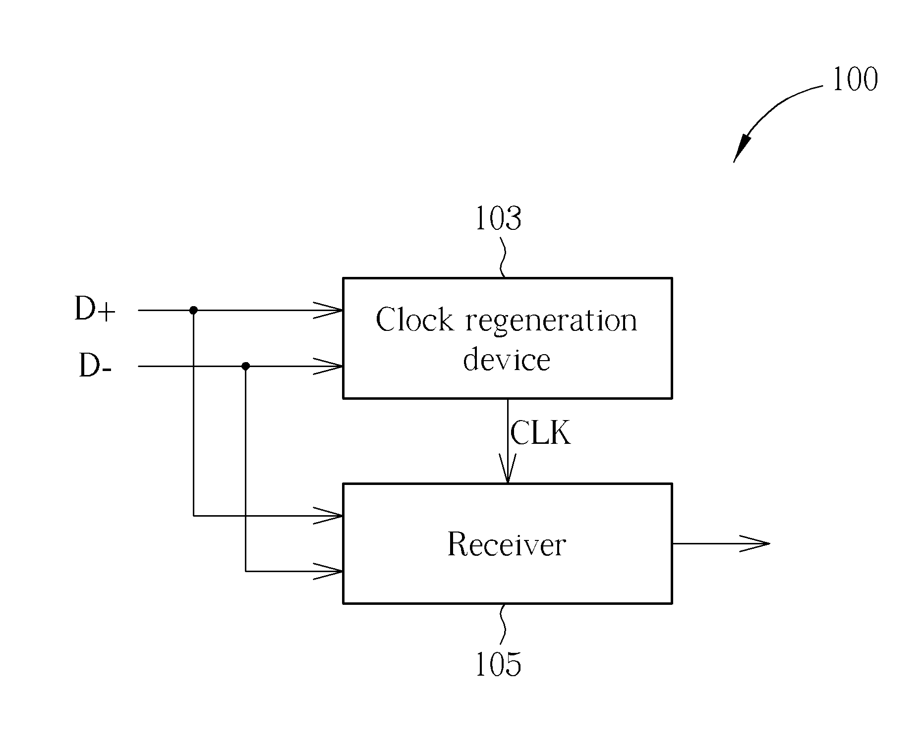
  • Figure 1
    Figure 1
  • Figure 2
    Figure 2
  • Figure 3
    Figure 3
Patent Text Reader

Abstract

A clock regeneration method, for generating a clock signal for being utilized by a receiver / transceiver / receiver system / transceiver system, includes: performing data / pattern detection on at least one input signal to generate recovered data; detecting at least one synchronization pattern in the input signal according to a synchronization pattern rule, and generating a synchronization signal corresponding to the synchronization pattern; and performing frequency-locking on the synchronization signal to generate the clock signal. More particularly, the step of detecting the at least one synchronization pattern in the input signal according to the synchronization pattern rule further comprises: detecting the at least one synchronization pattern by performing synchronization pattern detection on the recovered data. An associated reference-less receiver and an associated crystal-less system are also provided.
Need to check novelty before this filing date? Find Prior Art

Description

BACKGROUND OF THE INVENTION

[0001] 1. Field of the Invention

[0002] The present invention relates to Universal Serial Bus (USB) communication, and more particularly, to a clock regeneration method, an associated reference-less receiver, and an associated crystal-less system.

[0003] 2. Description of the Prior Art

[0004] Typically, the conventional receiver needs an external crystal oscillator, so the architecture thereof is complicated. More particularly, the external crystal oscillator is utilized as a source of a reference frequency, various problems may occur. For example, when the conventional receiver utilizes the external crystal oscillator as the source of the reference frequency, additional terminals and associated Electrostatic Discharge (ESD) protection circuits are needed, and therefore, additional costs are introduced. In addition, regarding the problems of the power consumption of the external crystal oscillator and switching noises, it seems unlikely that there is a good solut...

Examples

Embodiment Construction

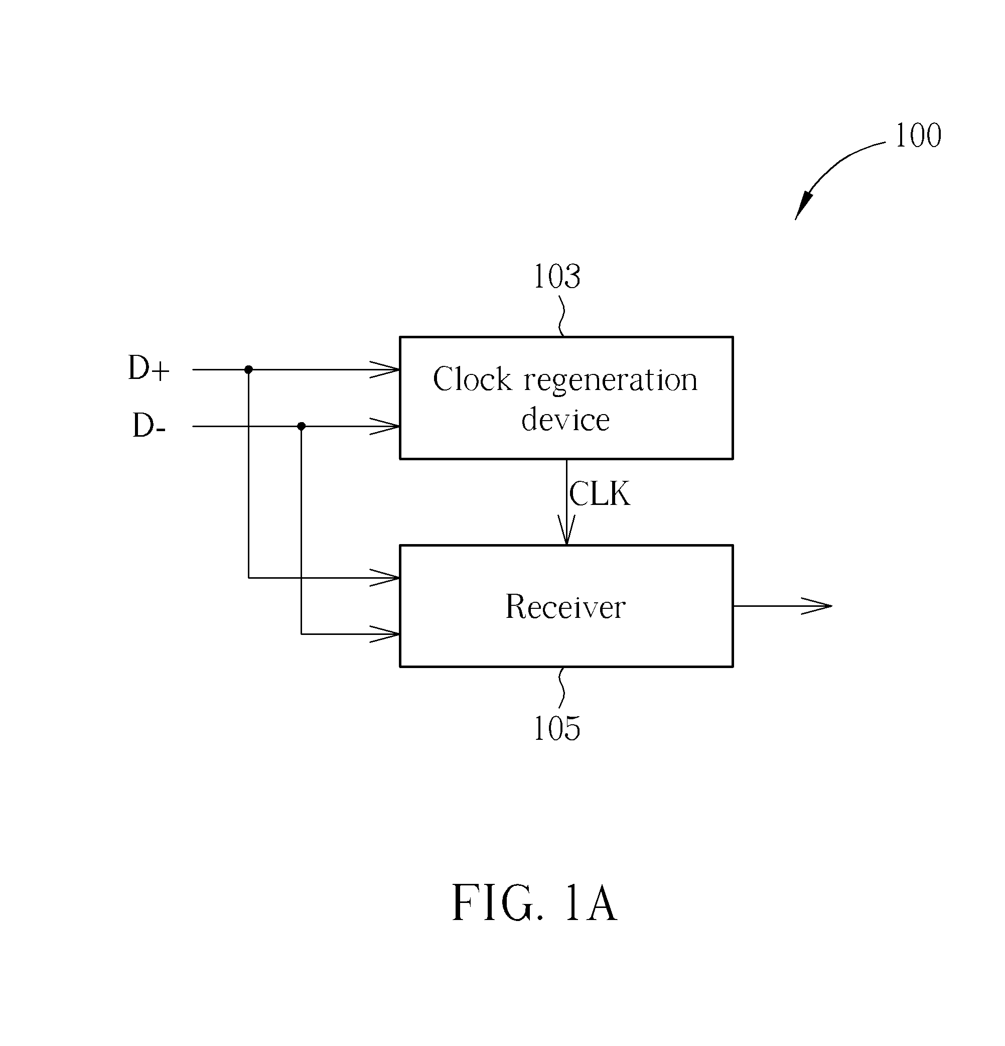
[0023]Please refer to FIG. 1A. FIG. 1A is a diagram of a crystal-less system 100 according to a first embodiment of the present invention. According to this embodiment, the crystal-less system 100 can be applied to various devices respectively complying with Universal Serial Bus (USB) 1.0, 1.1, and 2.0 standards, such as various kinds of portable electronic devices. As shown in FIG. 1A, the crystal-less system 100 comprises a clock regeneration device 103 and a receiver 105. Without introducing the side effects mentioned above, having no need to utilize any external crystal oscillator, the clock regeneration device 103 can generate the clock signal CLK of extremely high accuracy according to at least one input signal such as the input signals D+ and D− (which are a set of differential signals in this embodiment), for being utilized by the receiver 105. As a result, the crystal-less system 100 can achieve the best receiver performance by utilizing the clock signal CLK.

[0024]In this e...