Radiation detection device, radiographic apparatus and radiographic system

a detection device and radiographic technology, applied in the field of radiographic equipment and radiographic systems, can solve the problems of difficult to accurately manufacture a grating of a large size, difficult to obtain the intensity difference, and inability to obtain an image sufficient as an x-ray absorption image in soft biological tissue or soft material, etc., to achieve accurate interpolation of radiation phase information, maintain image quality, and expand the radiation exposure field

Inactive Publication Date: 2013-01-10
FUJIFILM CORP
View PDF2 Cites 24 Cited by
  • Summary
  • Abstract
  • Description
  • Claims
  • Application Information

AI Technical Summary

Benefits of technology

[0013]According to the aspect of the invention, each of the first grating and the second grating is constituted by a plurality of grating pieces, and the radiation exposure field can be easily expanded. At least one pixel is interposed between each pixel of the radiation image detector onto which the connection portion of two adjacent grating pieces of the first grating is projected and each pixel onto which the connection portion of two adjacent grating pieces of the second grating is projected, such that a pixel in which the phase information of radiation can be obtained can be provided around the pole of each pixel onto which the connection portion is projected. Therefore, it is possible to accurately interpolate the phase information of radiation in each pixel onto which the connection portion is projected by using the phase information of radiation in a pixel around the pole, and to maintain image quality.

Problems solved by technology

However, since the X-ray absorption ability of the material decreases as the atomic number of the element constituting the material decreases, there is a problem in that the contrast of an image sufficient as an X-ray absorption image is not obtained in a soft biological tissue or a soft material.
Accordingly, since the difference between their X-ray absorption amounts is small, it is difficult to acquire the intensity difference.
However, it is necessary that the first and second diffraction gratings have a high aspect ratio with a grating pitch in the order of μm, making it difficult to accurately manufacture a grating of a large size.

Method used


Image

  • Radiation detection device, radiographic apparatus and radiographic system
  • Radiation detection device, radiographic apparatus and radiographic system
  • Radiation detection device, radiographic apparatus and radiographic system

Examples


Embodiment Construction

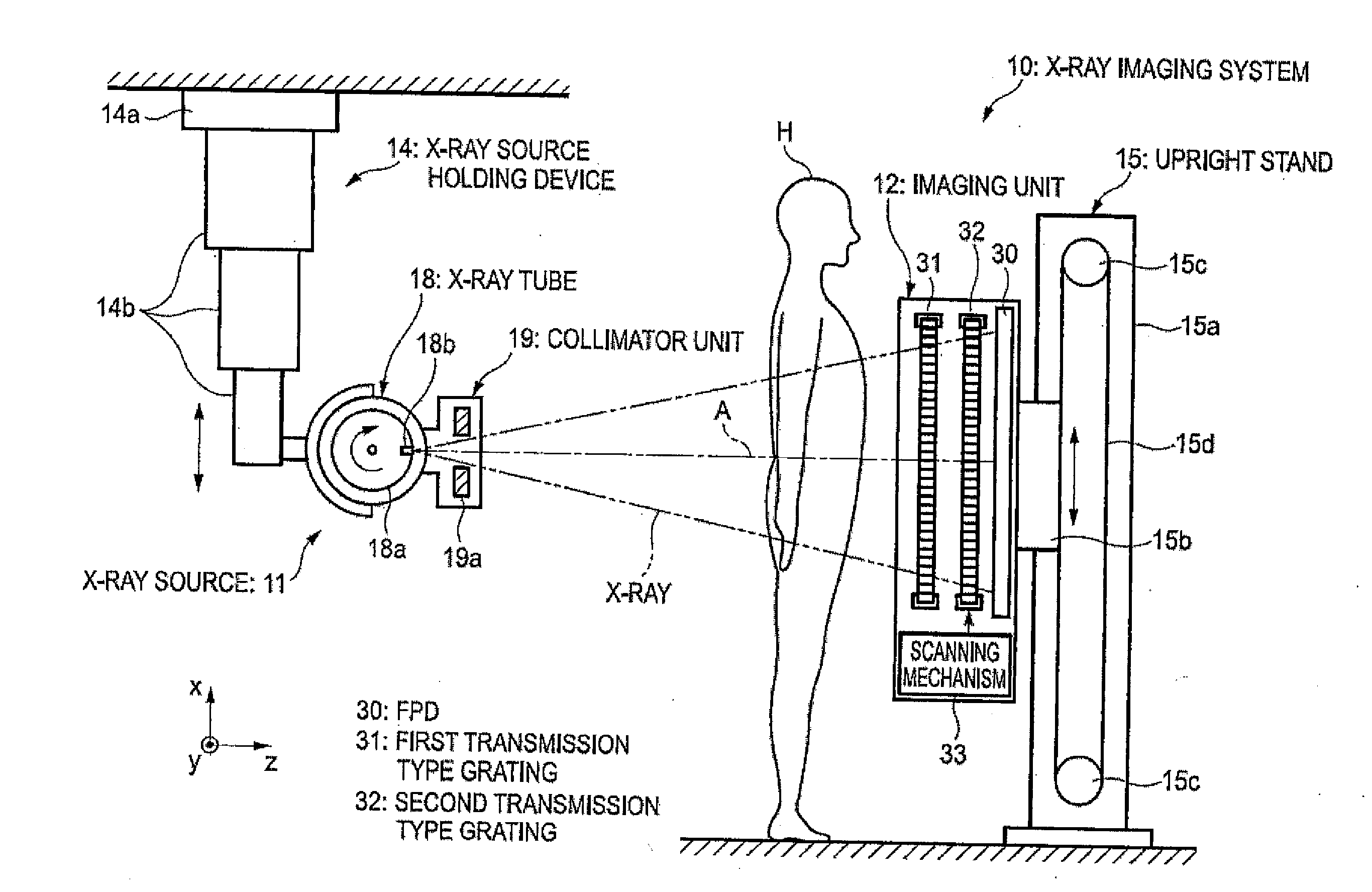
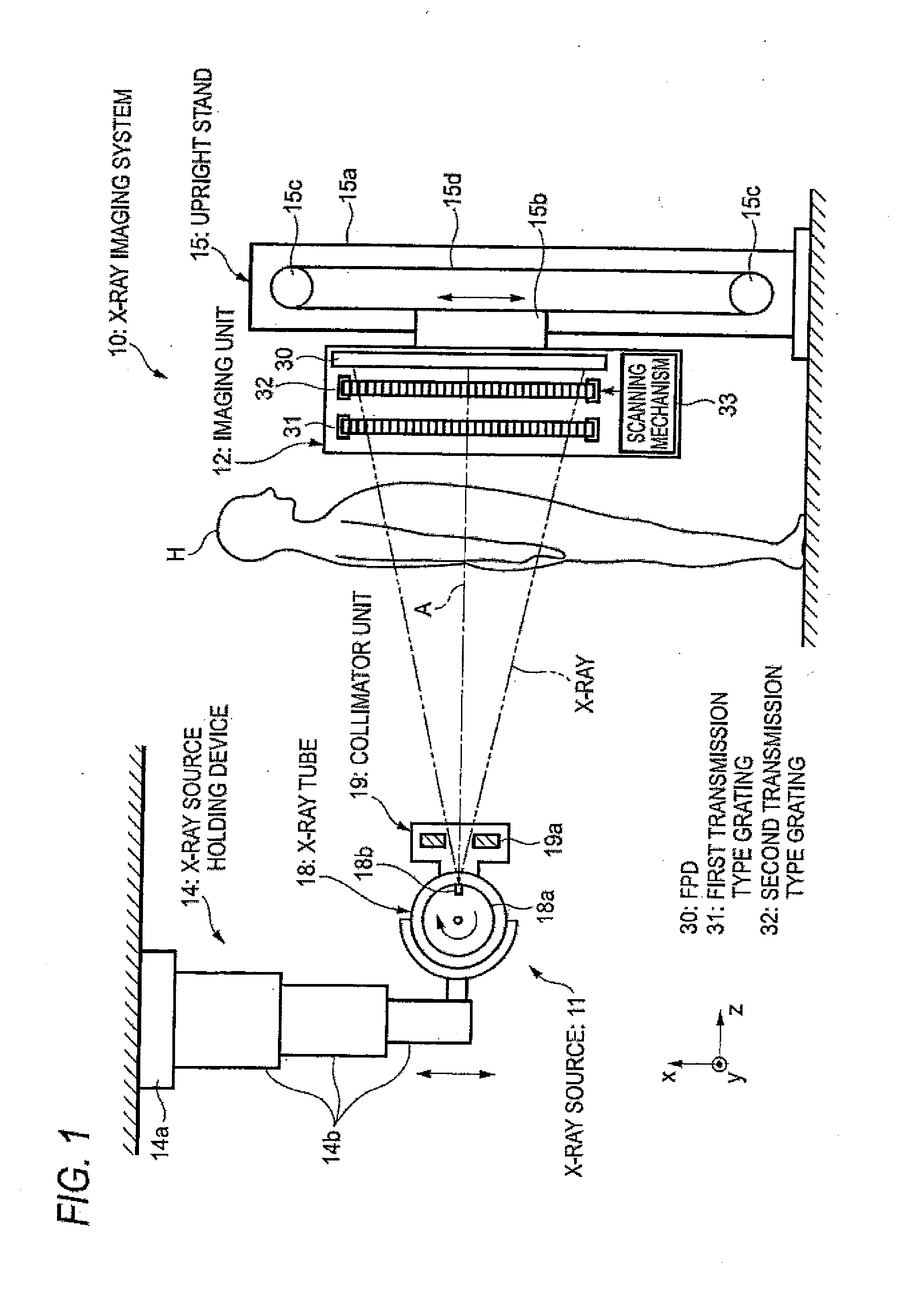
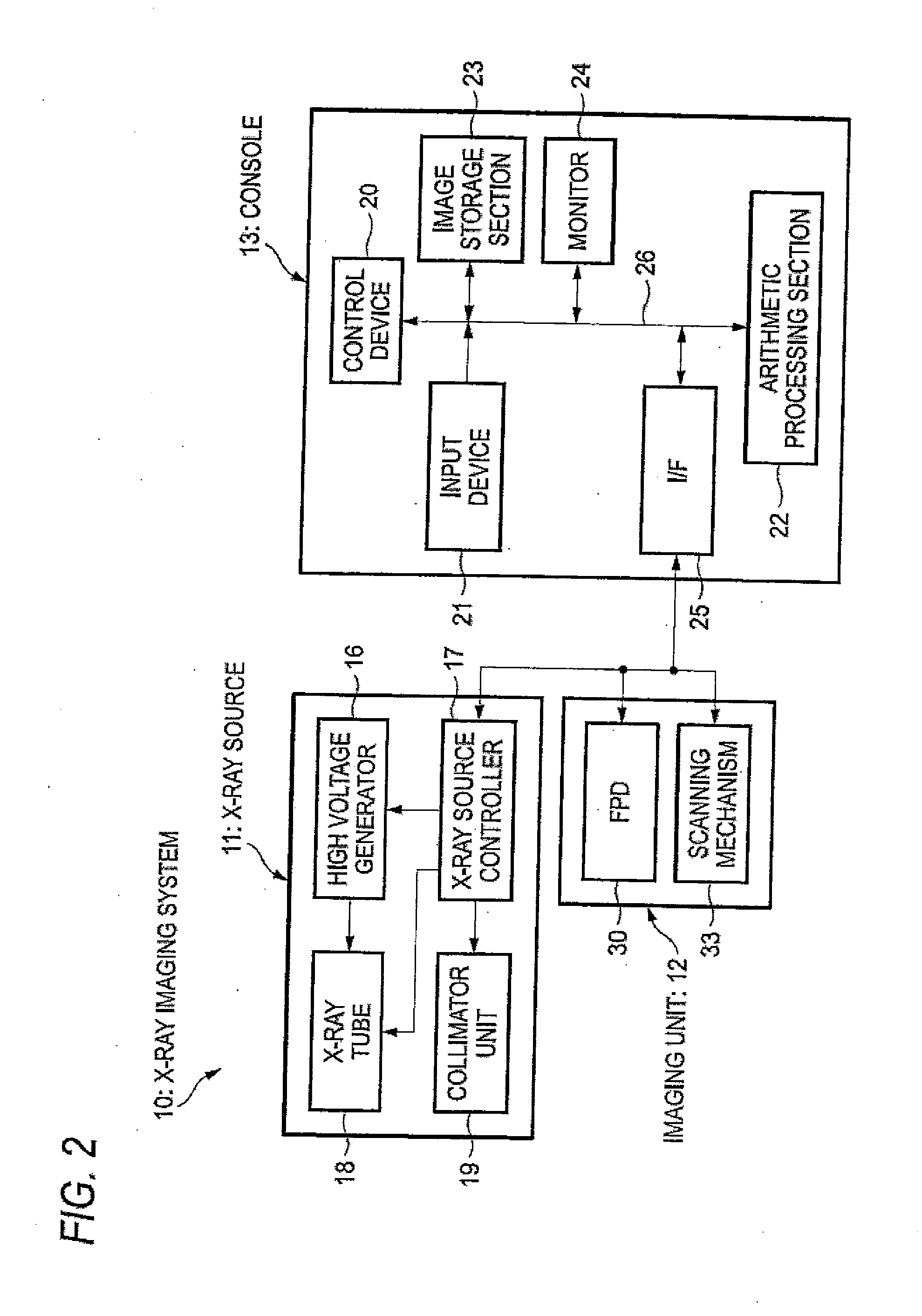
[0033]An X-ray imaging system 10 shown in FIGS. 1 and 2 is an X-ray diagnostic apparatus which images a subject (patient) H in a standing state and mainly includes: an X-ray source 11 which emits X-rays to the subject H; an imaging unit 12 which is disposed opposite the X-ray source 11 and which detects X-rays transmitted through the subject H from the X-ray source 11 and generates the image data; and a console 13 which controls an exposure operation of the X-ray source 11 or an imaging operation of the imaging unit 12 on the basis of an operation of the operator and which generates a phase contrast image by arithmetic processing of the image data acquired by the imaging unit 12.

[0034]The X-ray source 11 is held by an X-ray source holding device 14 suspended from the ceiling so as to freely move in a vertical direction (x direction). The imaging unit 12 is held by an upright stand 15 installed on the floor so as to freely move in the vertical direction.

[0035]The X-ray source 11 incl...


PUM

PropertyMeasurementUnit
distanceaaaaaaaaaa
tube voltageaaaaaaaaaa
thicknesses h1aaaaaaaaaa

Abstract

A radiographic system includes an X-ray source, a first transmission type grating, a second transmission type grating, a scanning mechanism, and a flat panel detector, and an arithmetic processing section. The first transmission type grating is constituted by connecting a plurality of first grating pieces in a first direction, and the second transmission type grating is constituted by connecting a plurality of second grating pieces in the first direction. In projection onto the flat panel detector with the focus of the X-ray source as a viewpoint, at least one pixel is interposed between each pixel of the flat panel detector onto which a connection point of two adjacent first grating pieces is projected and each pixel onto which a connection portion of two adjacent second grating pieces is projected.

Description

TECHNICAL FIELD[0001]The present invention relates to a radiation detection device which detects radiation, such as X-rays, having passed through a subject, and a radiographic apparatus and a radiographic system including the same.BACKGROUND ART[0002]X-rays are used as a probe for seeing through a subject since the X-rays are attenuated depending on the atomic number of an element, which forms a material, and the density and thickness of the material. Imaging using X-rays has been widespread in fields such as medical diagnosis and non-destructive inspection.[0003]In a general X-ray imaging system, a subject is disposed between an X-ray source which emits X-rays and an X-ray image detector which detects X-rays and a transmission image of the subject is captured. In this case, each X-ray emitted from the X-ray source toward the X-ray image detector is attenuated (absorbed) by the amount corresponding to the difference in properties (atomic number, density, and thickness) of materials ...

Claims


Application Information

Patent Timeline
Patent Type & Authority Applications(United States)
IPC IPC(8): G21K1/06G01N23/04
CPCA61B6/06G21K2201/06A61B6/484A61B6/4291G21K2207/005
Inventor TADA, TAKUJI
Owner FUJIFILM CORP
Why Eureka
Try Eureka