Optical component
a technology of optical components and components, applied in the field of optical components, can solve problems such as difficult optimization of elastic adhesives, and achieve the effect of suppressing thermal stress and mechanical external force, and reducing the degradation of optical characteristics
- Summary
- Abstract
- Description
- Claims
- Application Information
AI Technical Summary
Benefits of technology
Problems solved by technology
Method used
Image

Examples
embodiment 1
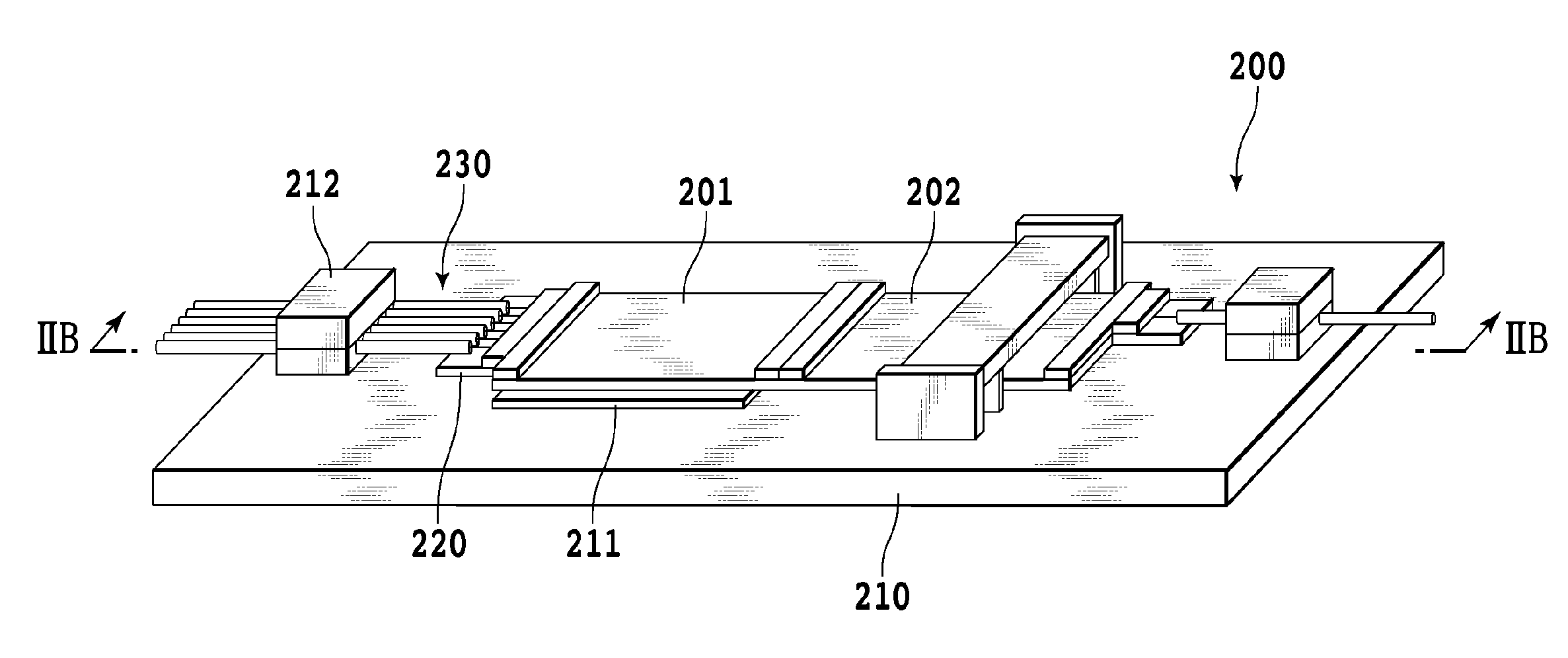
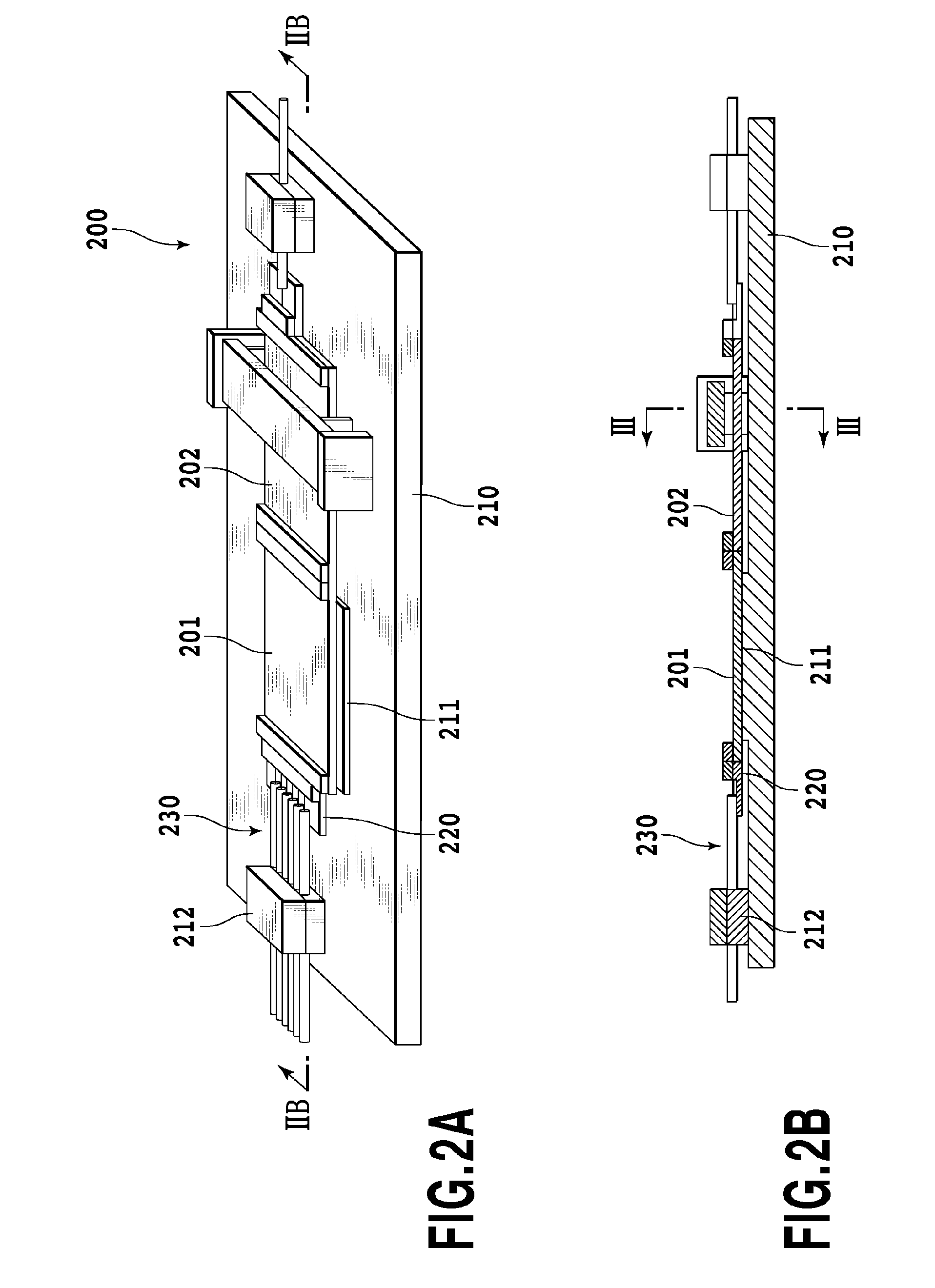
[0035]FIGS. 2A and 2B show an optical component according to an embodiment 1. An optical component 200 includes a first waveguide type optical device 201 such as a PLC, a second waveguide type optical device 202 butt jointed to the first waveguide type optical device 201, and amount 210 having a convex portion 211 to which the first waveguide type optical device 201 is directly fixed. The mount 210 includes an optical fiber holding member 212 formed thereon, and an optical fiber 230 is connected to the first waveguide type optical device 201 by using the optical fiber holding member 212 and an optical fiber aligning member 220 connected to the first waveguide type optical device 201. The second waveguide type optical device 202 is floated over the mount, and thereby, thermal stress attributed to a difference in thermal expansion between the second waveguide type optical device 202 and the mount 210 is suppressed against a connected portion of the waveguide type optical device and th...
embodiment 2
[0048]FIGS. 4A and 4B show an optical component according to an embodiment 2. An optical component 400 is greatly different from the optical component 200 of the embodiment 1 in that a presser support base and a mount are integrally formed as a case. Furthermore, the optical component 400 has a structure that three waveguide type optical devices are connected thereto.
[0049]The optical component 400 includes a first waveguide type optical device 401, a second waveguide type optical device 402 butt jointed to one end of the first waveguide type optical device 401, a third waveguide type optical device 402 butt jointed to the other end of the first waveguide type optical device 401, and a mount 410 having a convex portion 411 to which the first waveguide type optical device 401 is directly fixed. The mount 410 includes an optical fiber holding member 412 and an optical fiber 430 is connected to the second waveguide type optical device 402 by using the optical fiber holding member 412 a...
embodiment 3
[0058]FIG. 6 shows an optical component according to an embodiment 3. An optical component 600 is not of a type that multiple waveguide type optical devices are connected as described in the embodiments 1 and 2 but of a type that a spatial phase modulator as a spatial optical component and a waveguide type optical device are optically coupled.
[0059]The optical component 600 includes a waveguide type optical device 601 and a mount 610 having a convex portion 611 to which a part of the waveguide type optical device 601 is directly fixed. The mount 610 includes an optical fiber holding member 612 formed thereon and an optical fiber 630 is connected to the waveguide type optical device 601 by using an optical fiber holding member 612 and an optical fiber aligning member 620 connected to the waveguide type optical device 601. An unfixed part of the waveguide type optical device 601 is floated over the mount 610, and thereby, thermal stress attributed to a difference in thermal expansion ...
PUM
 Abstract
Description
Claims
Application Information
 - R&D
- Intellectual Property
- Life Sciences
- Materials
- Tech Scout
- Unparalleled Data Quality
- Higher Quality Content
- 60% Fewer Hallucinations
Browse by: Latest US Patents, China's latest patents, Technical Efficacy Thesaurus, Application Domain, Technology Topic, Popular Technical Reports.
© 2025 PatSnap. All rights reserved.Legal|Privacy policy|Modern Slavery Act Transparency Statement|Sitemap|About US| Contact US: help@patsnap.com