This helps you quickly interpret patents by identifying the three key elements:
Problems solved by technology
Method used
Benefits of technology
Benefits of technology
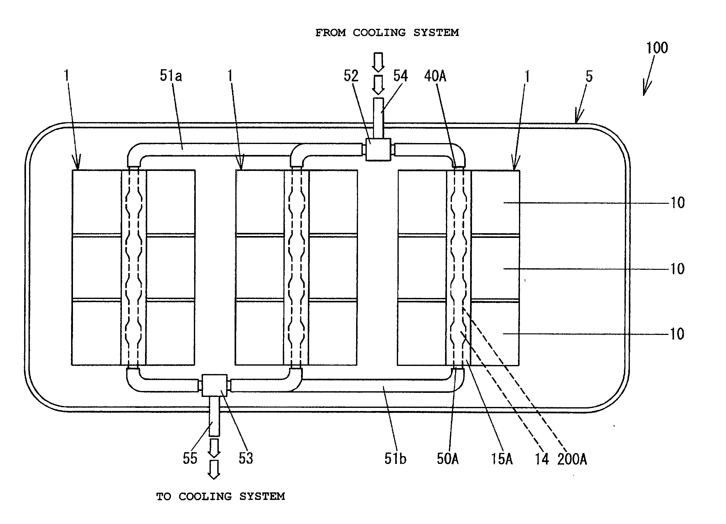
The present invention is about a method of cooling down multiple cells simultaneously using a heat transferpipe. The refrigerant is forced to repeatedly speed up and slow down, which prevents the formation of a thermal boundary layer and encourages uniform temperature distribution across the cooling plate. This results in more uniform charging and discharging of the cells, which increases their lifespan and reduces variability in their performance.
Problems solved by technology
As a result, the plurality of cells arranged on the surface of the cooling plate cannot be evenly cooled.
Method used
Image
Click on the blue label to locate the original text in one second.
Reading with bidirectional positioning of images and text.
Examples
first embodiment
[0045]Hereinafter, a description will be given of a battery module and an power supply apparatus according to embodiments of the present invention with reference to the accompanying drawings.
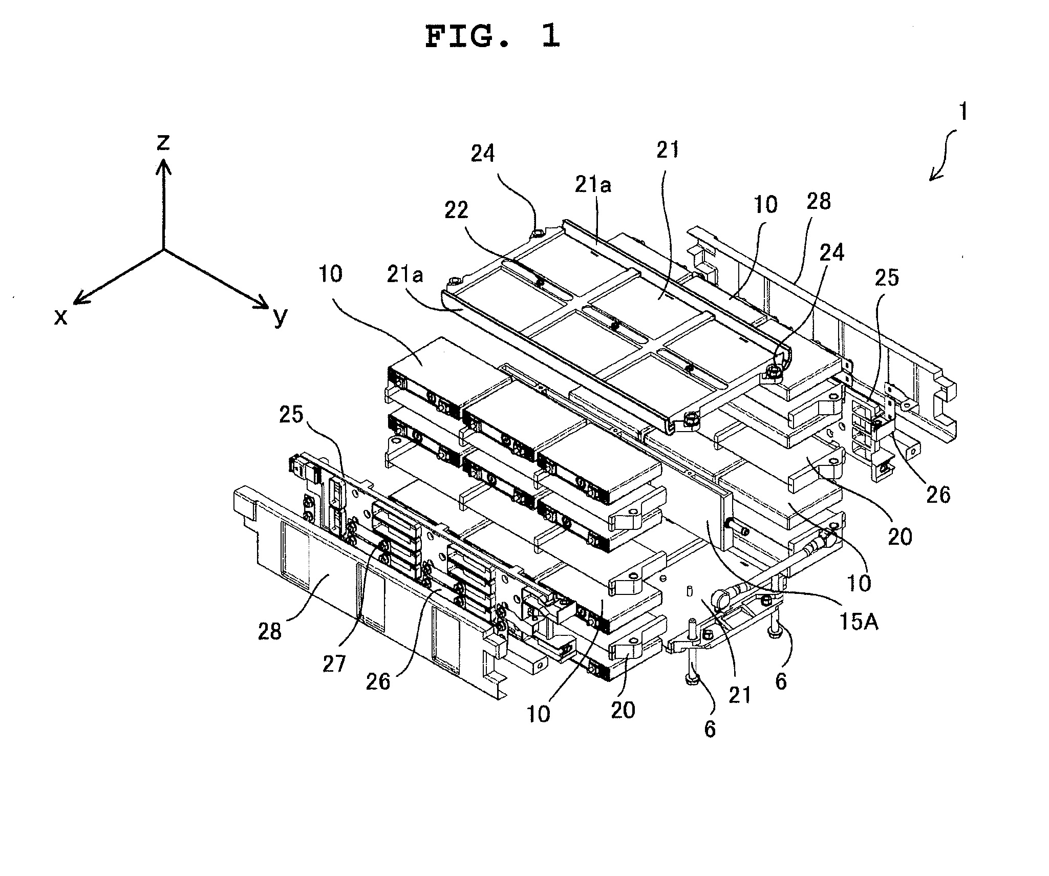
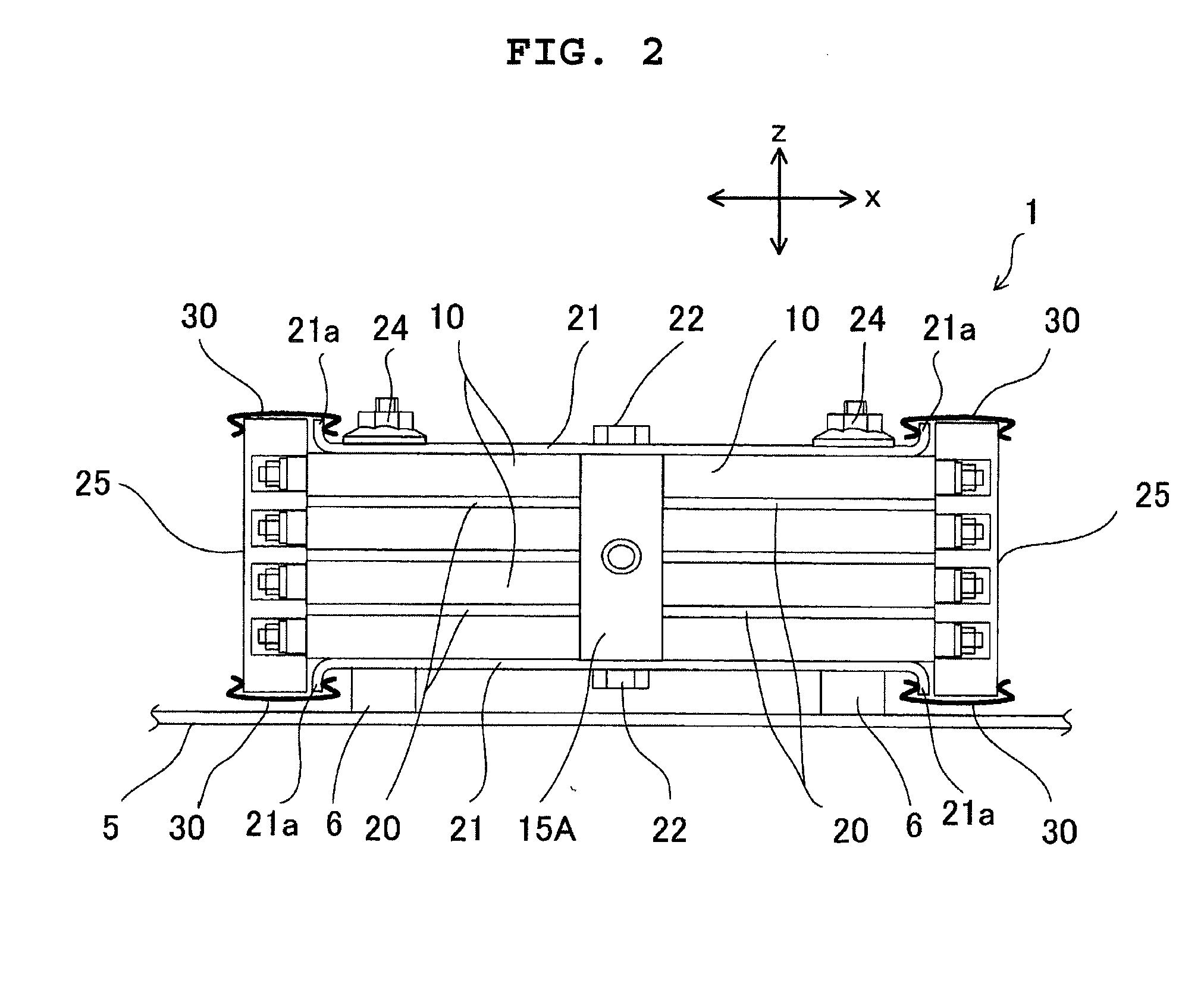
[0046]FIG. 1 is an exploded perspective view illustrating a battery module 1 according to a first embodiment of the present invention, and FIG. 2 is a front view illustrating the battery module 1 illustrated in FIG. 1, viewed from a front side. In FIG. 2, covers 28 that will be described later is omitted.
[0047]The battery module 1 includes a large number of cells 10. As illustrated in FIG. 1, it is assumed that a depth direction is an x-direction, a longitudinal direction is a y-direction, and a height direction is a z-direction. A cooling plate 15A is disposed in a substantially center of the battery module 1 in the x (depth) direction. The cooling plate 15A has a plate shape having a front surface with a size in the z (height) direction larger than that in the x (depth) direction, and lateral ...
second embodiment
[0101]A second embodiment of the present invention will be described with reference to FIG. 18. FIG. 18 is a cross-sectional view illustrating a cooling plate 15B according to the second embodiment of the present invention. In FIG. 18, the same or corresponding parts as those in the first embodiment are denoted by identical reference numbers attached with B, and differences therebetween will be mainly described. In a heat transferpipe 200B according to the second embodiment, as in the first embodiment, large diameter pipes 201B and small diameter pipes 202B are alternately arranged. However, in the heat transferpipe 200B according to the second embodiment, no widening pipes and no thinning pipes are interposed between the large diameter pipes 201B and the small diameter pipes 202B.
[0102]A length L1 of the small diameter pipes 202B and a length L2 of the large diameter pipes 201B are appropriately set from the viewpoints of the pressure loss and the heat transfer, or from the viewp...
third embodiment
[0110]A third embodiment of the present invention will be described with reference to FIG. 20. FIG. 20 is a cross-sectional view illustrating a cooling plate 15C according to the third embodiment of the present invention. In FIG. 20, the same or corresponding parts as those in the first embodiment are denoted by identical reference numbers attached with C, and differences therebetween will be mainly described.
[0111]In the third embodiment, three heat transfer pipes 200C each having large diameter pipes 201C and small diameter pipes 202C alternately arranged are arranged in the z (height) direction of the cooling plate 15C. The respective heat transfer pipes 200C are disposed in parallel to each other. With this configuration, the temperature variability of the cooling plate 15C in the z (height) direction can be also reduced. The number of heat transfer pipes 200C is appropriately set according to the layout of the cells 10.
[0112]Therefore, according to the third embodiment, in addi...
PUM
Abstract
Equalization of a temperature distribution in a flow direction on a cooling plate is facilitated so that temperatures of plural cells that thermally contact with the cooling plate are equalized, to reduce variability in the state of charge-discharge and the lifetimes of the respective cells. A battery module includes a cooling plate having a refrigerant channel in which a refrigerant circulates, and plural cells that are thermally conductively coupled onto a surface of the cooling plate, in which the refrigerant channel is formed with plural large diameter pipes that decelerate the refrigerant, and plural small diameter pipes that accelerate the refrigerant, a channel sectional area of the large diameter pipes is larger than a refrigerant channel sectional area of the small diameter pipes arranged on an inflow side of the large diameter pipes.
Description
BACKGROUND OF THE INVENTION[0001]1. Technical Field[0002]The present invention relates to a battery module having a plurality of chargeable and dischargeable battery cells connected to each other, and more particularly to a cooling structure for the battery module.[0003]2. Background Art[0004]The battery module mounted in hybrid vehicles and electric vehicles is configured by a combination of a large number of secondary batteries such as a lithiumionbattery cell, a nickelhydridebattery cell, or a nickel-cadmiumbattery cell. Charge and discharge currents of the battery module are generally large, and heat generation is also increased, as a result of which a temperature rise of the battery cell per se also increases. The temperature rise in the battery cell needs to be reduced as much as possible so as to be rapidly cooled from the view point of the lifetime of battery.[0005]As a method of rapidly cooling the battery cell, there is a method using a refrigerant. There has been kno...
Claims
Application Information
Patent Timeline
Application Date:The date an application was filed.
Publication Date:The date a patent or application was officially published.
First Publication Date:The earliest publication date of a patent with the same application number.
Issue Date:Publication date of the patent grant document.
PCT Entry Date:The Entry date of PCT National Phase.
Estimated Expiry Date:The statutory expiry date of a patent right according to the Patent Law, and it is the longest term of protection that the patent right can achieve without the termination of the patent right due to other reasons(Term extension factor has been taken into account ).
Invalid Date:Actual expiry date is based on effective date or publication date of legal transaction data of invalid patent.

