

Performance line display unit
a technology of display unit and performance line, which is applied in the direction of instruments, structural/machine measurement, transportation and packaging, etc., can solve the problems of reducing derricking angle, not determining how much the suspended load can be moved, and not determining the operation limi
- Summary
- Abstract
- Description
- Claims
- Application Information
AI Technical Summary
Benefits of technology
Problems solved by technology
Method used
Image

Examples
embodiment 1
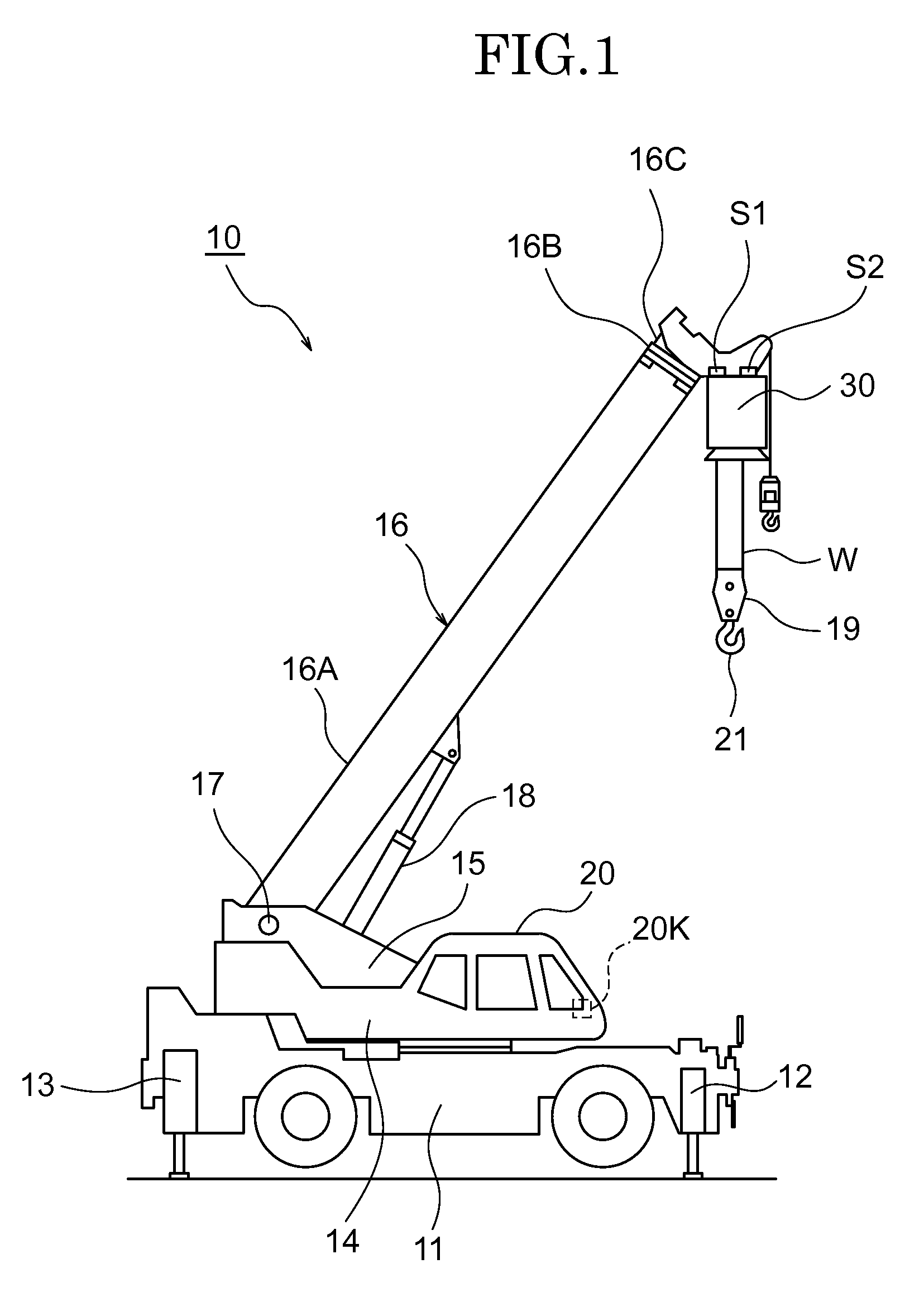
[0036]FIG. 1 illustrates a rough terrain crane 10 as a crane equipped with a performance line display unit. This rough terrain crane 10 includes a carrier 11 as a main body of a vehicle having a running operation, a pair of front outriggers 12 provided on the right and left of the front side of the carrier 11, a pair of back outriggers 13 provided on the right and left of the back side of the carrier 11, a rotation platform 14 attached on the carrier 11 in a horizontally rotatable manner, a cabin 20 provided in the rotation platform 14 and an extensible boom 16 attached to a bracket 15 fastened to the rotation platform 14.
[0037]The base end section of the extensible boom 16 is attached to the bracket 15 via a supporting shaft 17. The extensible boom 16 can be raised and lowered about the supporting shaft 17. A cylinder 18 for raising and lowering the extensible boom is provided between the bracket 15 and the extensible boom 16. The extensible boom 16 is raised and lowered by the exp...
embodiment 2
[0076]FIG. 5 illustrates a screen (display) 133A of a monitor (display unit) 133 according to Embodiment 2. FIG. 9B is a block diagram illustrating a constitution of a control system according to Embodiment 2.
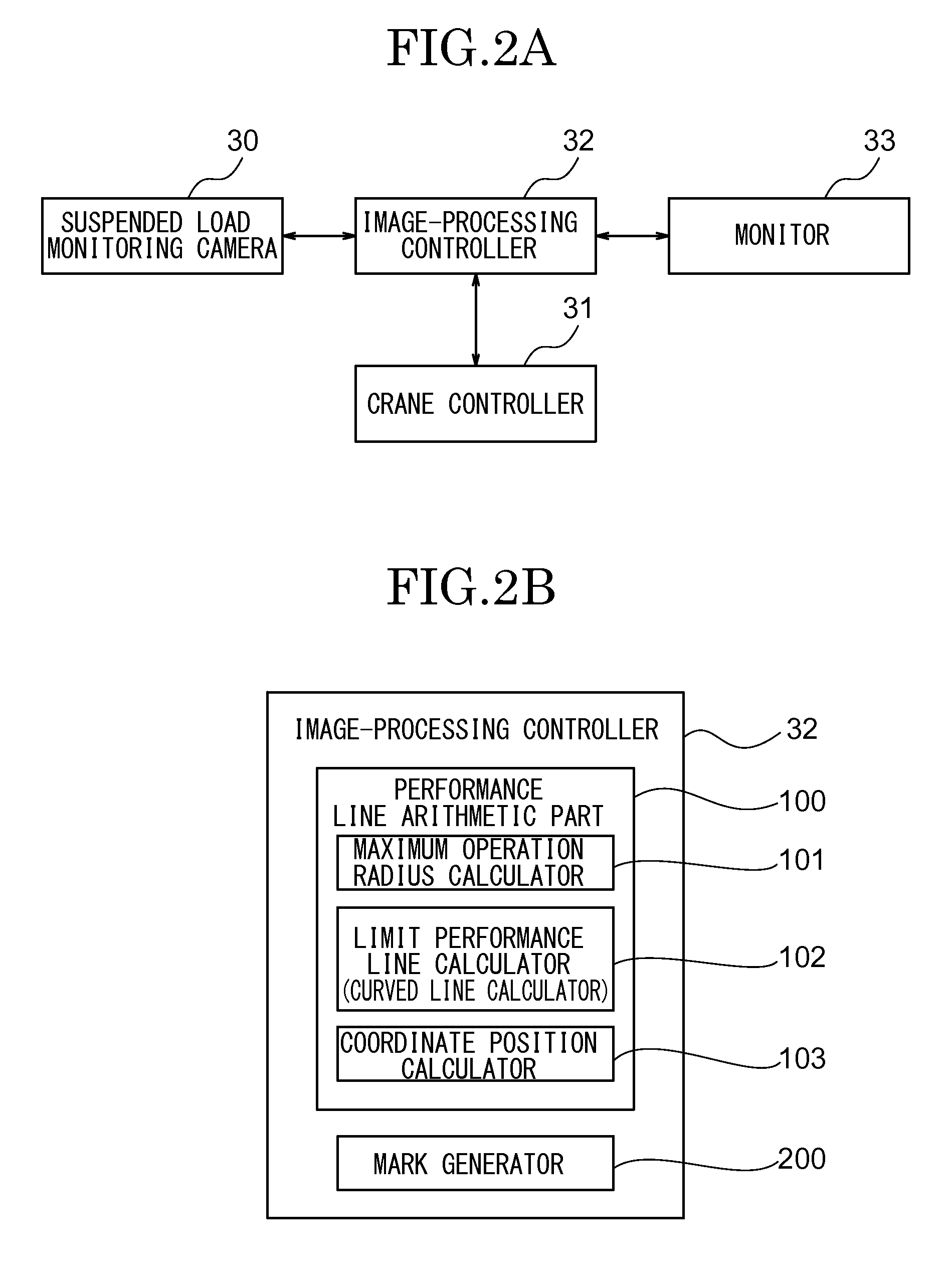
[0077]In this Embodiment 2, an image-processing controller 300 includes a performance line arithmetic part 400.
[0078]The performance line arithmetic part 400 includes a maximum operation radius calculator 401 which obtains the maximum operation radius in an actual load based on the actual load and the projection amount of each of the outriggers 12, 13, a limit performance line calculator 402 which obtains a limit performance line R1 illustrating the range of the maximum operation radius obtained by the maximum operation radius calculator 401, a graphic image generator 403 which generates a graphic image Rg illustrating the limit performance line R1 with the rotation axis O1 of the crane 10 as an original point, an imaging range detector 404 which obtains an imaging range imaged...
embodiment 3
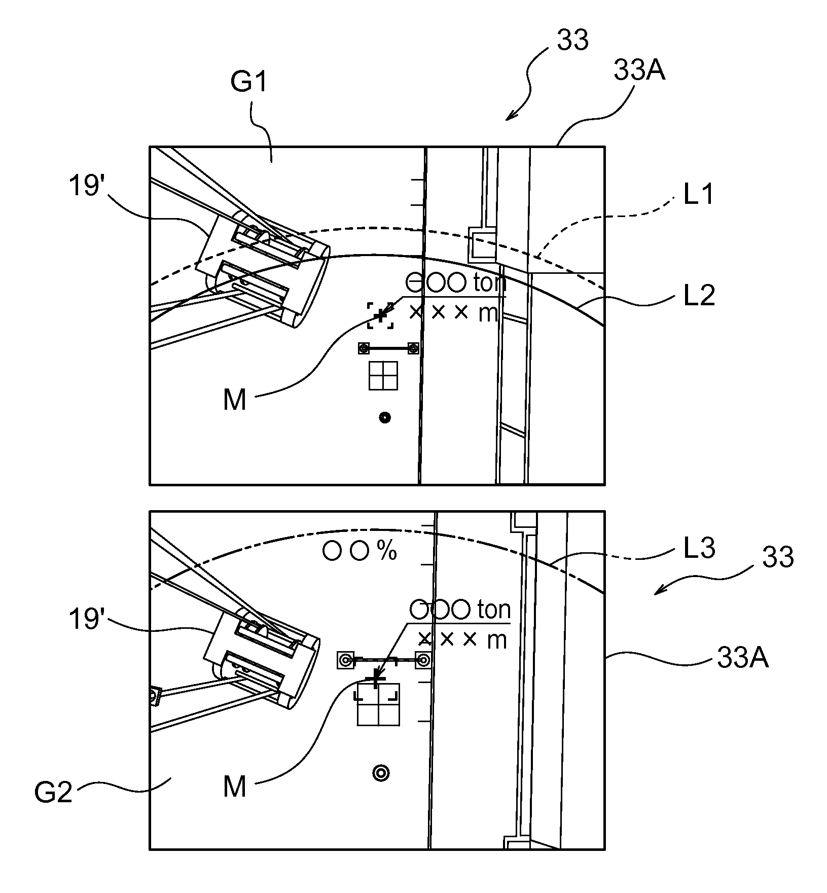
[0091]FIGS. 10A, 10B are views each illustrating a screen 233A of a monitor 233 according to Embodiment 3. In Embodiment 3, a graphic image Ea illustrating a boom is overlapped with an image Gc photographed by the suspended load-monitoring camera 30 to be displayed on the screen 233A of the monitor 233.
[When a Load is Not Suspended]
[0092]When a load is not suspended, as illustrated in FIG. 10A, a limit performance line La illustrating an area of a maximum operation radius in which the extensible boom 16 can move with the present length, the maximum load which can be suspended in the maximum operation radius, and a 90% performance line Lb illustrating a 90% load ratio relative to the maximum suspended load are overlapped with the image Gc to be displayed. “00 ton” and the present length of the extensible boom 16 are displayed on the screen 233A since the load is not suspended.
[0093]The load movable area can be confirmed by the screen 233A without suspending a load.
[0094]When the maxi...
PUM
 Abstract
Description
Claims
Application Information