Ultrasonic transducer for use in a fluid medium

a technology of ultrasonic transducers and fluid mediums, applied in the direction of mechanical vibration separation, liquid/fluent solid measurement, instruments, etc., can solve the problems of reducing affecting the operation of ultrasonic transducers, and affecting the quality of ultrasonic transducers, so as to speed up the decaying of vibrations of the transducer core, reduce natural vibrations, and improve the effect of mass production

Inactive Publication Date: 2013-01-17
ROBERT BOSCH GMBH
View PDF2 Cites 14 Cited by
  • Summary
  • Abstract
  • Description
  • Claims
  • Application Information

AI Technical Summary

Benefits of technology

[0021]The coring out or the at least one hollow space may also be filled up entirely or partially, if required, using at least one acoustic damping element, for instance, an acoustic damping material, and thus at least reduce natural vibrations of the housing, for example, of the sleeve, for example, and disturbing structure-borne noise transmissions. This damping element or damping material may, for example, be fully or partially identical to a damping material which even in today's ultrasonic transducers is applied to the backside of the transducer core, in order to speed up the decaying of vibrations of the transducer core. For example, it may be a damping molding material. In this context, the damping molding material may hook mechanically into the hollow space, for instance, “clutch” into it, so that even in the case of poor adhesion to the housing, a displacement of the interior of the transducer in the direction of the measuring medium or in the opposite direction is ...

Problems solved by technology

In particular, during the manufacture of ultrasonic transducers having a sealing foil, but also in the case of other types of ultrasonic transducers, in practice, a multitude of technical challenges occurs.
One technical challenge ...

Method used


Image

  • Ultrasonic transducer for use in a fluid medium
  • Ultrasonic transducer for use in a fluid medium
  • Ultrasonic transducer for use in a fluid medium

Examples


Embodiment Construction

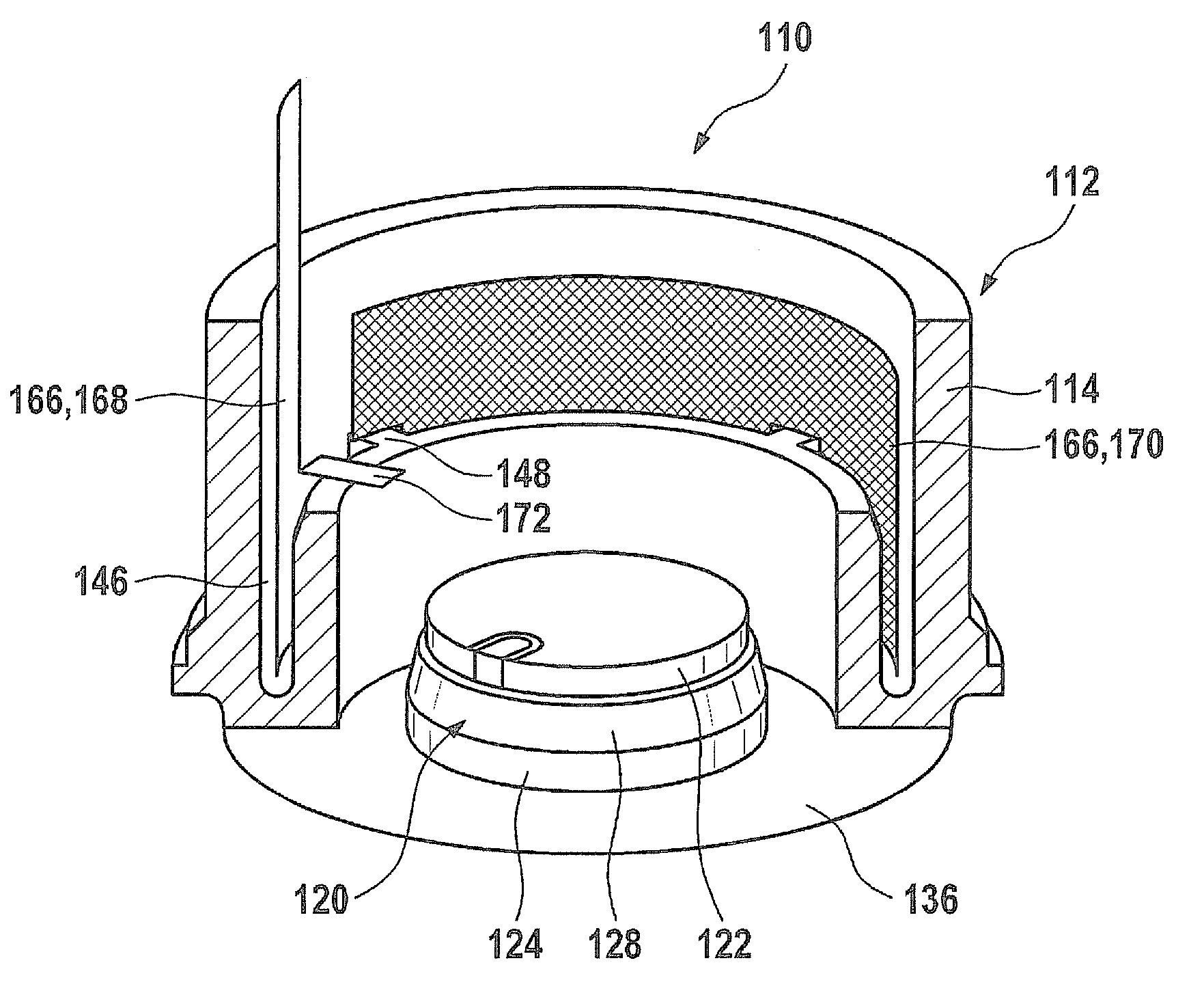
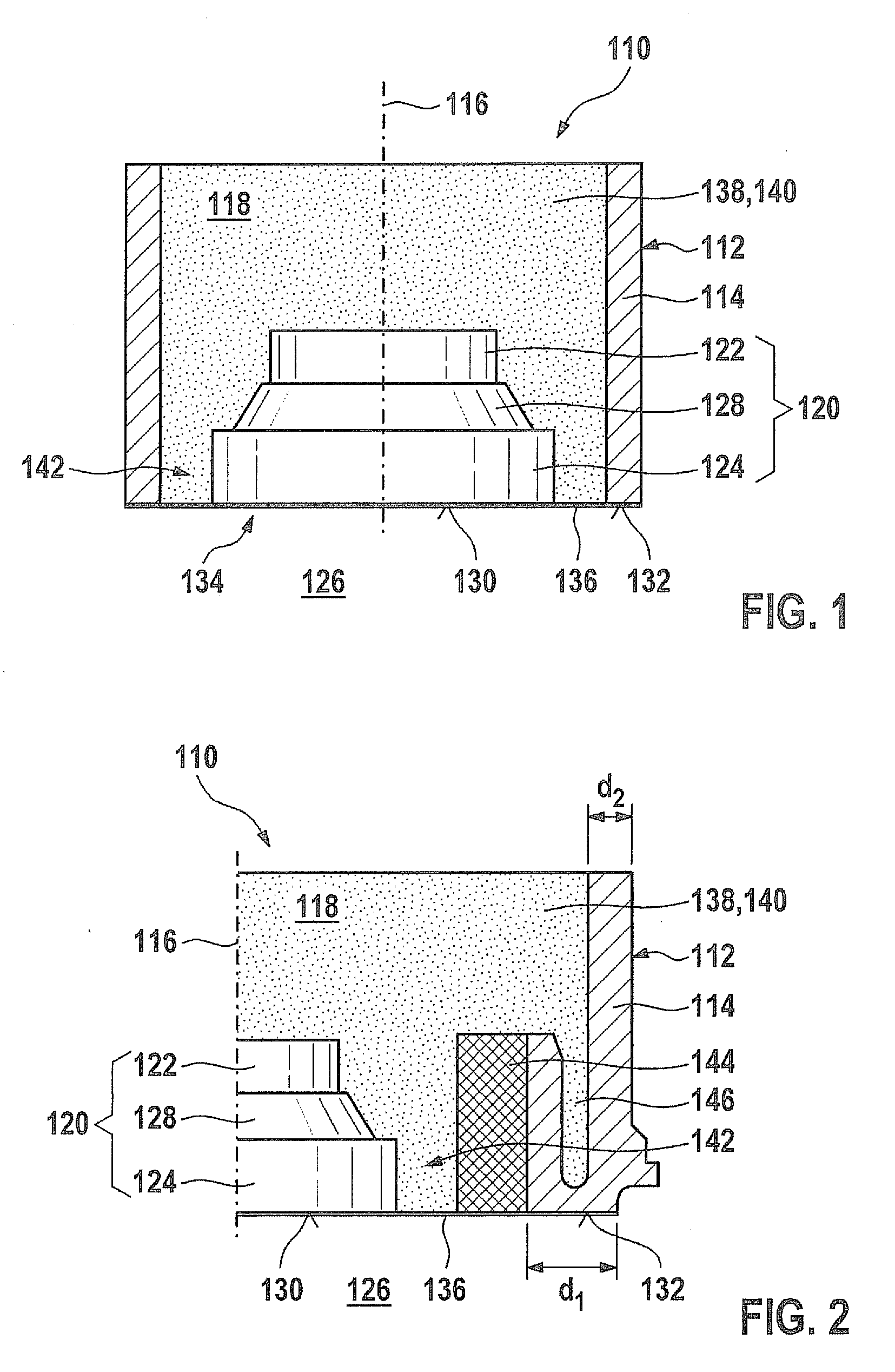
[0028]In a sectional representation from the side, FIG. 1 shows an example of a usual ultrasonic transducer 110 in a greatly simplified specific embodiment. Ultrasonic transducer 110 includes a housing 112 having a housing wall 114. Housing 112 is only indicated symbolically in FIG. 1, and may be aligned axially symmetrical to an axis 116, for example. Housing 112 encloses an interior space 118, in which a transducer core 120 is accommodated. Transducer core 120 includes an electroacoustic transducer element 122, such as a piezoelectric transducer element, as well as an adaptation element 124 on the side of transducer core 120 facing a fluid medium. Adaptation element 124 is used for the impedance matching to the acoustic impedance of fluid medium 126, and may be developed according to the related art mentioned above. Furthermore, in the exemplary embodiment shown, between adaptation element 124 and electroacoustic transducer element 122, a compensating element 128 is optionally sit...


PUM


Abstract

An ultrasonic transducer for use in a fluid medium includes at least one housing, e.g., a sleeve, which has at least one interior space, and at least one transducer core having at least one electroacoustic transducer element is accommodated in the interior space. The housing has a housing wall at least partially enclosing the transducer core using at least one hollow space.

Description

BACKGROUND OF THE INVENTION[0001]1. Field of the Invention[0002]The present invention relates to an ultrasonic transducer for use in a fluid medium.[0003]2. Description of the Related Art[0004]Various types of ultrasonic transducers are known from the related art. By ultrasonic transducer one should generally understand, in this context, an element that is in a position to generate ultrasonic waves and / or pick up such ultrasonic waves and to convert them to electrical signals. Ultrasonic transducers are used, for instance, in fluid media for flow measurement, such as in the intake manifold or exhaust-gas tract of internal combustion engines, or in other fields of use, such as fluid-level sensors. Flow measurements may be undertaken, for example, by systems having two or more ultrasonic transducers, for instance, by evaluating running time differences. Examples of ultrasonic transducers are shown in published German patent application document DE 10 2007 010 500 A1, or in German pate...

Claims


Application Information

Patent Timeline
IPC IPC(8): G01F1/66
CPCB06B1/0655G01F1/662G10K11/004G01N29/222G01N29/2437G01F23/296
Inventor MUELLER, ROLANDHUEFTLE, GERHARDHORSTBRINK, MICHAELLANG, TOBIASRADWAN, SAMIKUENZL, BERNDWANJA, ROLAND
Owner ROBERT BOSCH GMBH
Why Eureka
Try Eureka