Method of Wastewater Treatment and Apparatus for its Realization in Sequencing Batch Reactors

a batch reactor and wastewater treatment technology, applied in water/sludge/sewage treatment, biological water/sewage treatment, construction, etc., can solve problems such as head loss, achieve the effects of reducing water level, reducing hydraulic delivery of air-lift pump, and improving delivery yield

Inactive Publication Date: 2013-01-17
TOPOL JAN
View PDF2 Cites 4 Cited by
  • Summary
  • Abstract
  • Description
  • Claims
  • Application Information

AI Technical Summary

Benefits of technology

[0010]Water from the sub-surface layer is drawn into the separate tank over the overflow of the decanting apparatus by reducing the water level in the air-lift pump tank. Hydraulic delivery of the air-lift pump is reduced by hydraulic losses resulting from the water flowing through the decanting apparatus. These hydraulic losses in aggregate will show as a head loss, which is a difference between the water level in the reactor and the water level in the separate tank. The head loss is a sum of the overflow height in the decanting apparatus above the water level in the reactor and the head loss by the water flow through the decanting apparatus. It applies that head loss due to the flow increase with the increasing flow (1 / sec, 1 / min) and decreasing diameter of the pipes of the decanting apparatus. If the head loss reaches the height equal to the submerge depth of the flexible connection of the decanting apparatus to the air-lift pump tank, i.e. the water level in the air-lift pump tank falls below this connection, the decanting apparatus will be filled with air and discontinues its operation.
[0011]The wastewater treatment plant with a sequencing batch reactor according to the invention consists of a tank of the reactor with the inlet of wastewater, an aerator and an air-lift pump for the pumping off of the treated water. The air-lift pump is located in a separate tank, separated in a watertight way from the inside of the reactor. The pumped off water is drawn off from the reactor to the separate tank by the decanting apparatus, consisting of an inlet pipe in the upper inflow part, equipped with a float component, an overflow and an inlet pipe. The lower end of the inlet pipe is flexibly connected with the separate tank. The overflow is kept by the float component above the water level in the reactor. The inlet opening of the inlet pipe is submerged below the water level in the reactor in order to avoid pollution by floating impurities during the decanting of the treated water. As it applies for the air-lift pump that the more it is submerged, the higher its delivery yield, the location of the inlet opening is usually chosen to be in the lower section of its tank, no matter whether this tank is located inside or outside the reactor. The depth of the air-lift pump inlet is selected according to the required delivery yield of the air-lift pump.

Problems solved by technology

These hydraulic losses in aggregate will show as a head loss, which is a difference between the water level in the reactor and the water level in the separate tank.

Method used


Image

  • Method of Wastewater Treatment and Apparatus for its Realization in Sequencing Batch Reactors
  • Method of Wastewater Treatment and Apparatus for its Realization in Sequencing Batch Reactors
  • Method of Wastewater Treatment and Apparatus for its Realization in Sequencing Batch Reactors

Examples


Embodiment Construction

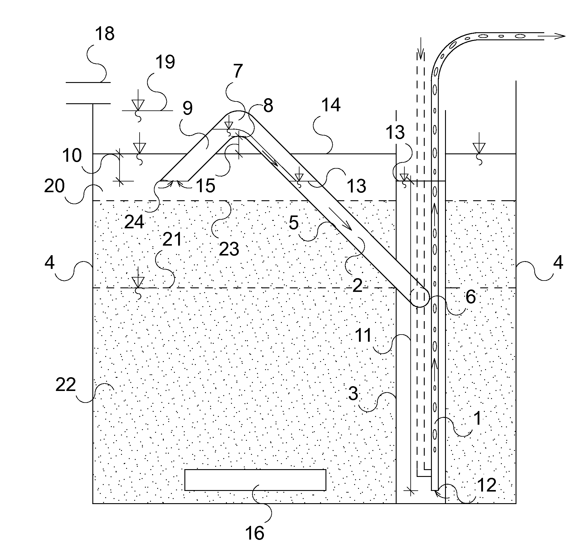
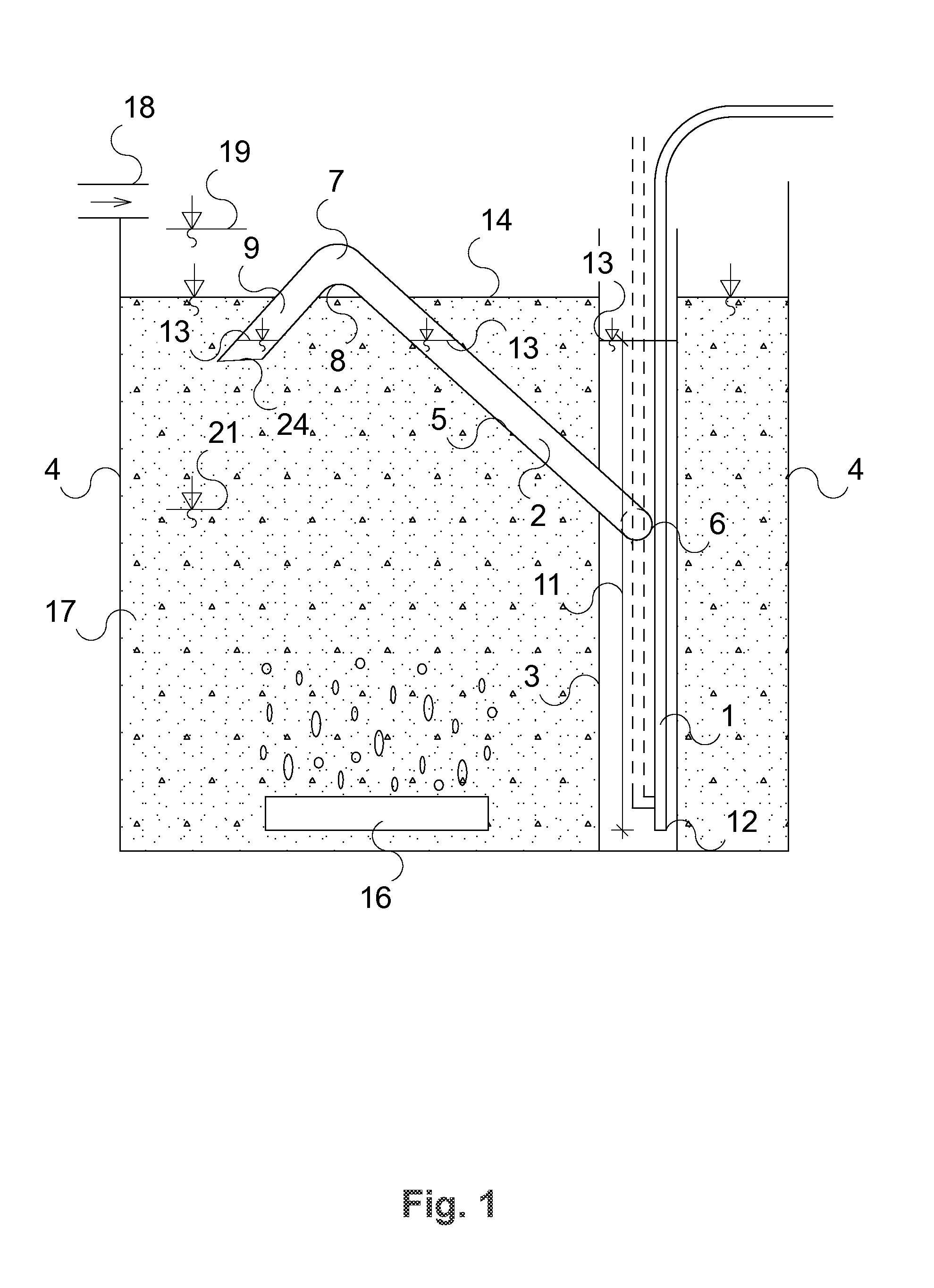
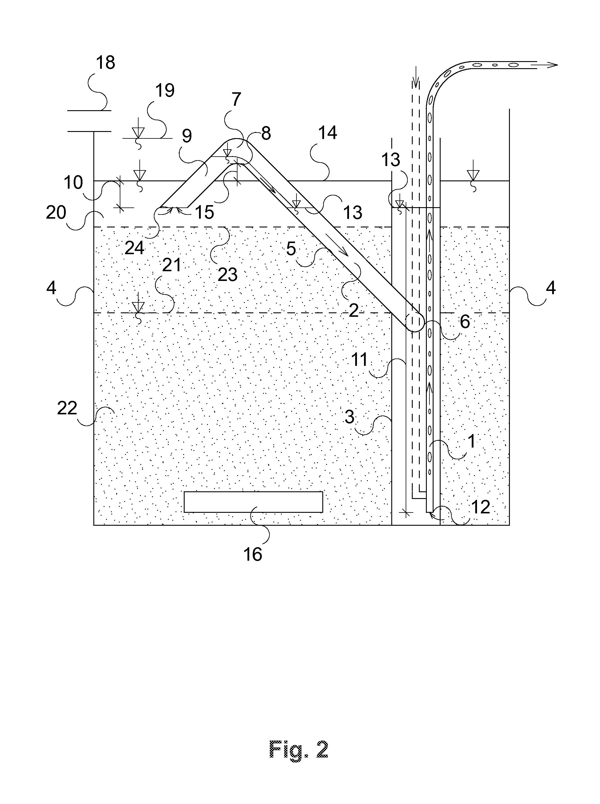
[0015]Based on the invention, the wastewater treatment plant consists of the reactor 4 with a gravitational or pressure inlet 18 of wastewater and the aerator 16. In one of the possible versions shown in FIGS. 1 and 2 the reactor 4 houses a decanting apparatus 2, consisting of an inlet pipe 9 with an inlet opening 24, a float component 7 and also a transport pipe 5, entering the tank 3 via flexible connection 6. The float component 7 can comprise for instance a pipe bend or an aired part of another shape. The flexible connection 6 can consist of a turning bend, a flexible pipe made of a soft material, etc. The tank 3 of the air-lift pump 1 is separated from the inside of the reactor 4 in a watertight way. The air-lift pump 1 has its inlet 12 advantageously located near the bottom of the tank 3. For the air-lift pump 1 to operate reliably its inlet 12 should not be placed above the minimum water level 21 in the reactor 4, reduced by half of the difference between the upper and lower ...


PUM

PropertyMeasurementUnit
depthaaaaaaaaaa
depthaaaaaaaaaa
flexibleaaaaaaaaaa

Abstract

The method of wastewater treatment and the method-applying apparatus in the sequencing batch reactors, where after separating the activated sludge from the treated water the treated water is drawn off via a decanting apparatus from the sub-surface layer of water in the reactor. The decanted water is conveyed by the decanting apparatus to a separate tank, which is separated in a watertight way from the inside of the reactor. The treated water is pumped off from the separate tank to the outlet by the air-lift pump, the inlet of which is located at the level corresponding to the delivery yield of the air-lift pump. The submerged inlet part of the decanting apparatus moves vertically alongside with the fluctuating water level in the reactor.

Description

TECHNICAL FIELD[0001]The invention concerns the wastewater treatment in discontinuous flow reactors, i.e. in SBR (Sequencing Beach Reactor). Thus, it concerns the process of biological wastewater treatment using suspension of activated sludge mainly in small scale and domestic wastewater treatment plants.BACKGROUND ART[0002]The wastewater treatment in SBRs is characteristic by having divided the treatment process in several phases. During the first phase of filling, the water in the reactor rises from the lower to the upper level. The main treatment processes associated with aeration and mixing of wastewater with the activated sludge, consisting of the mixture of various microorganisms are performed after the reactor is filled to the upper level, that means to the operating level. The treatment processes can be started also during filling of the reactor. After the time needed for treatment of wastewater the sedimentation phase follows in which the activated sludge that is heavier th...

Claims


Application Information

Patent Timeline
Patent Type & Authority Applications(United States)
IPC IPC(8): C02F3/12
CPCC02F3/223C02F3/1263Y02W10/10
Inventor TOPOL, JAN
Owner TOPOL JAN
Why Eureka
Try Eureka