
Organic Light Emitting Display Device

a light-emitting display and organic technology, applied in the direction of organic semiconductor devices, thermoelectric devices, solid-state devices, etc., can solve the problems of poor blue light emission characteristics, high fabrication cost, and difficulty in large-size display fabrication, and achieve the effect of preventing color chang

Active Publication Date: 2013-01-17
LG DISPLAY CO LTD
View PDF2 Cites 26 Cited by
  • Summary
  • Abstract
  • Description
  • Claims
  • Application Information

AI Technical Summary

Benefits of technology

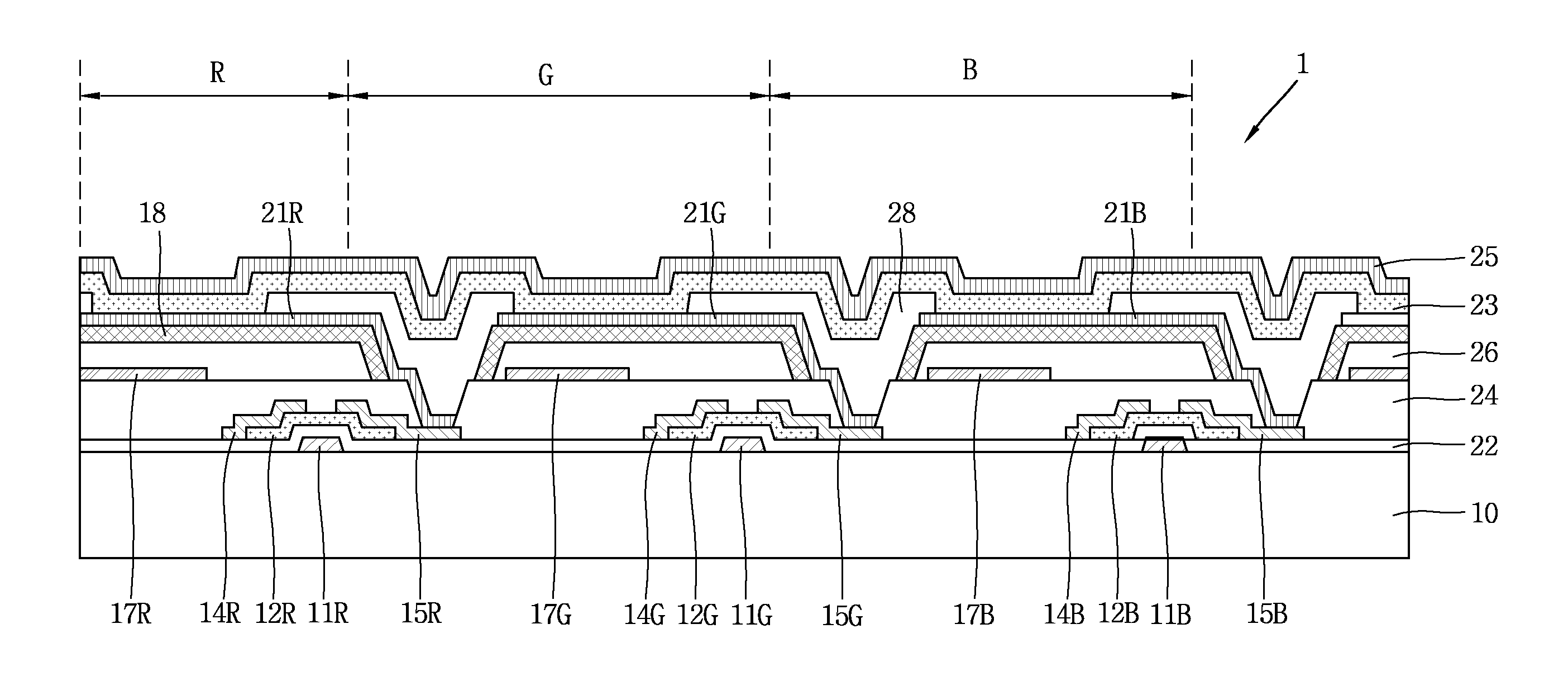
The present invention is about an organic light emitting display device that uses a special layer to compensate for the path and phase differences of emissive lights. This results in synchronized cavity peaks and prevents color change.

Problems solved by technology

Such displays are difficult to fabricate with a large-size display, have poor blue light emission characteristics, and have high fabrication cost.
However, in the case of an organic light emitting display device for emitting white color, the locations of luminescent materials (or emission layers) for emitting red light, green light and blue light are different, thereby causing difficulty in coinciding cavity peak phases for each wavelength.
As a result, variation between a cavity peak and a photoluminescence peak may occur, thereby causing a problem of reducing image quality.

Method used

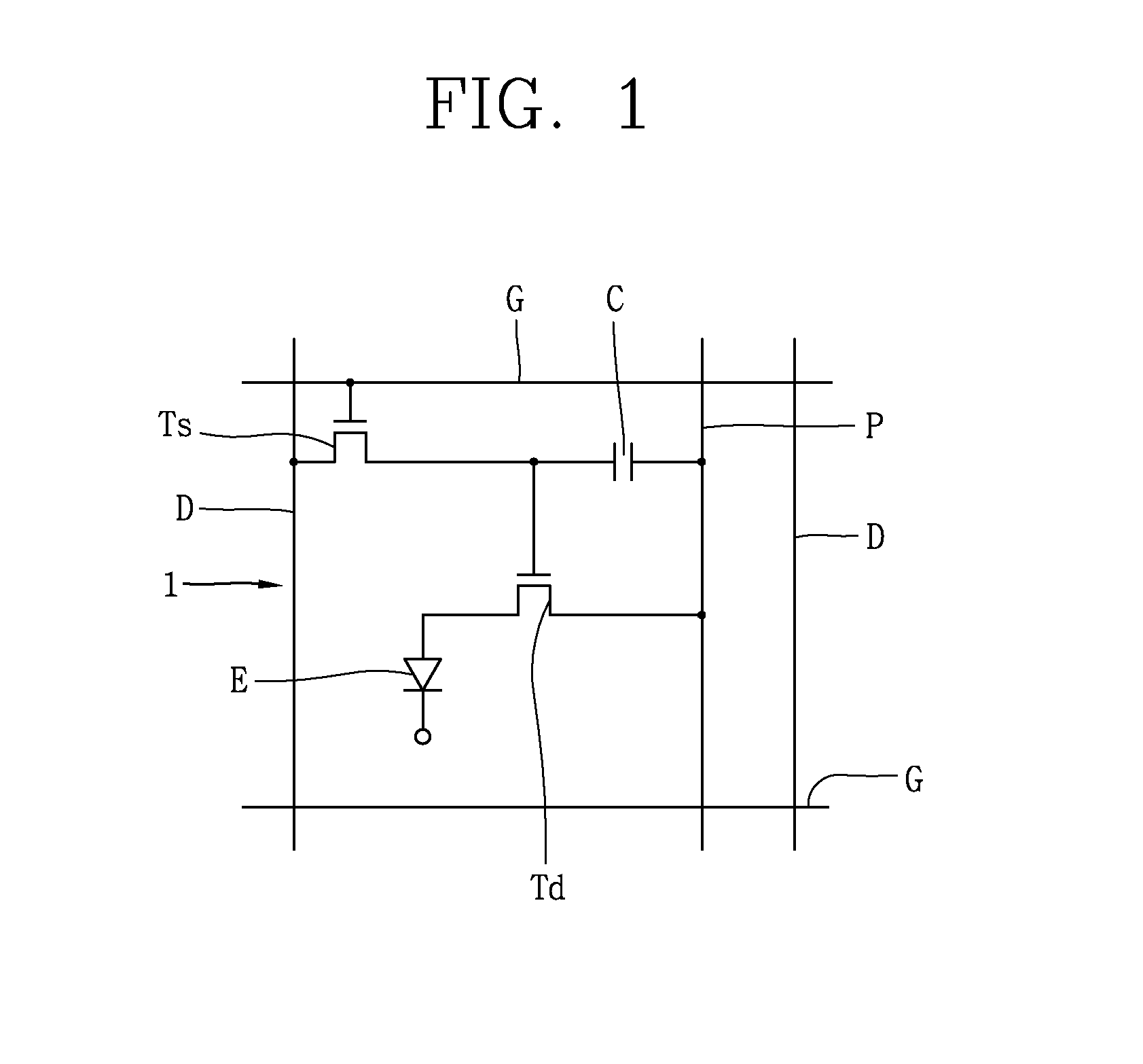
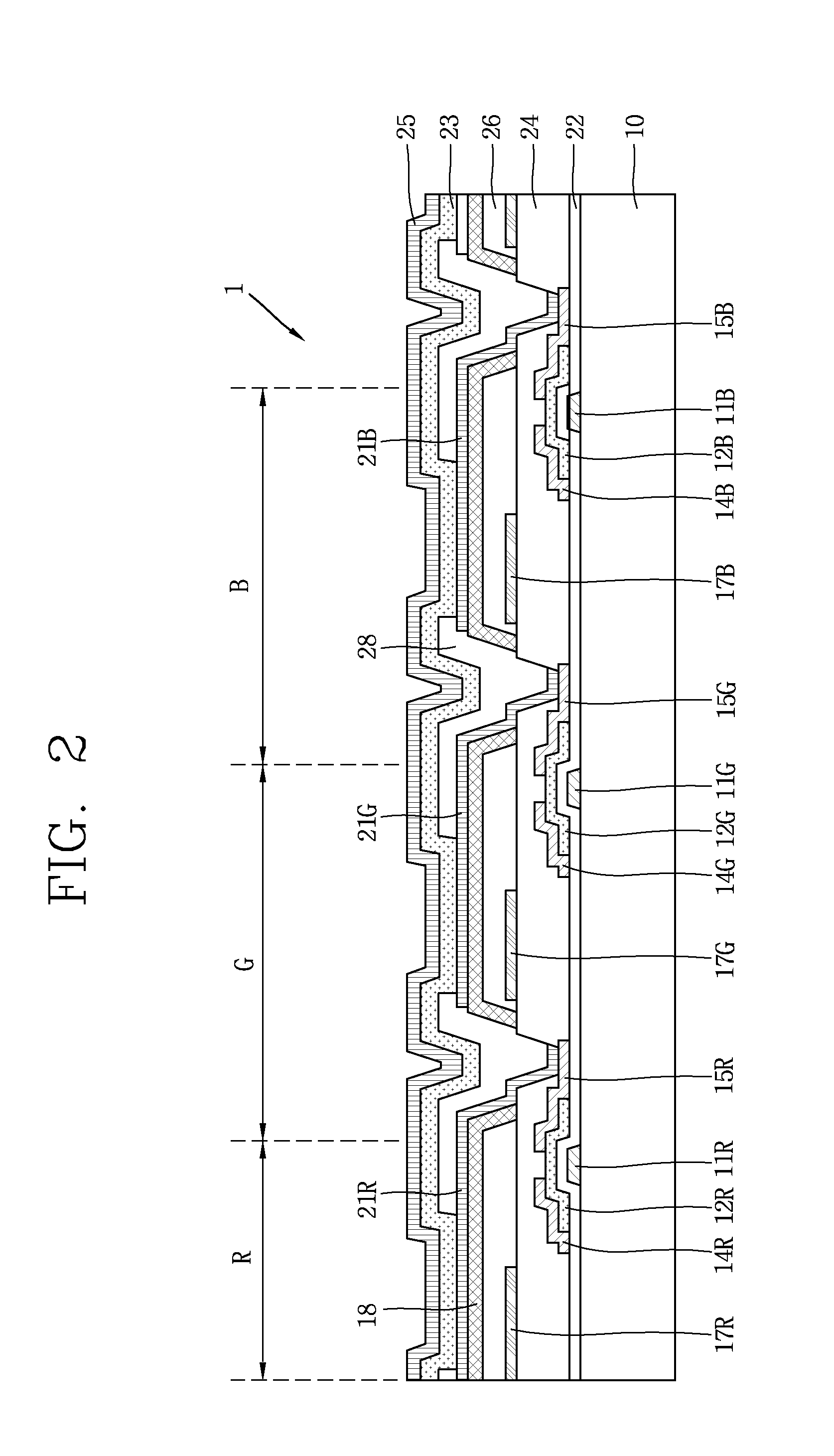

Image

  • Organic Light Emitting Display Device
  • Organic Light Emitting Display Device
  • Organic Light Emitting Display Device

Examples


Embodiment Construction

[0018]Reference will now be made in detail to embodiments of the present invention, examples of which are illustrated in the accompanying drawings.

[0019]According to example embodiments of the present invention, when luminescent materials for emitting red, green and blue are deposited to emit white light, color changes occurring due to the mismatch of cavity peaks can be prevented. In general, mismatched cavity peaks may be caused by a phase and path difference between light emitted from each luminescent material and light reflected by a reflective layer in the organic light emitting unit. Accordingly, if a thickness of the light emitting unit is drastically increased, then it may be possible to control a phase between light emitted from each luminescent material and light reflected by a reflective layer to coincide a phase difference between both of them, but in this case, the thickness of the light emitting unit is increased, and thus, the thickness of the entire organic light emi...


PUM


Abstract

An organic light emitting display device is provided to avoid color change due to a viewing direction. The organic light emitting display includes a light compensation layer having a refractive index different than that of an insulating layer. The organic light emitting display may be disposed at the side to which light emitted from an organic light emitting layer is entered to change the path and phase of light, thereby coinciding cavity peak phases for each wavelength of white light emitted from an organic light emitting unit.

Description

[0001]This application claims the benefit of Korean Patent Application No. 10-2011-0070579, filed in Korea on Jul. 15, 2011, which is hereby incorporated by reference.BACKGROUND OF THE INVENTION[0002]1. Field of the Invention[0003]The present invention relates to an organic light emitting display device, and more particularly, to an organic light emitting display device that prevents color change due to a viewing angle direction.[0004]2. Discussion of the Related Art[0005]In recent years, since an organic light emitting display device has been developed using poly-phenylene vinylene (PPV), which is a conjugate polymer, studies on organic materials such as a conjugate polymer having good conductivity have been active. Studies for applying such an organic material to a thin-film transistor, a sensor, a laser, a photoelectric element, and the like have been continuously carried out, and among them studies on organic light emitting display devices have been most active.[0006]In case of ...

Claims


Application Information

Patent Timeline
Patent Type & Authority Applications(United States)
IPC IPC(8): H01L27/15
CPCH01L27/3213H01L51/5275H01L2251/558H01L27/322H10K59/351H10K59/38H10K2102/351H10K59/879H10K59/35H10K50/16H10K50/171H10K50/858
Inventor KIM, SHIN-HANAHN, BYUNG-CHULTAK, YOON-HEUNGHAN, CHANG-WOOKKIM, DO-HYUNGLEE, JAE-MANCHOI, HONG-SEOKBAE, SUNG-JOONJOUNG, SEUNG-RYONG
Owner LG DISPLAY CO LTD
Learn More