Optical Spectrometer with Underfilled Fiber Optic Sample Interface

a fiber optic sample and optical spectrometer technology, applied in the direction of optical radiation measurement, instruments, spectrometry/spectrophotometry/monochromators, etc., can solve the problem of not being able to measure the intensity value of the optical spectrometer in the same direction, and the time dependencies that exceed the acceptable limits of a useful optical spectrometer,

Active Publication Date: 2013-01-17
THERMO ELECTRON SCI INSTR
View PDF5 Cites 8 Cited by
  • Summary
  • Abstract
  • Description
  • Claims
  • Application Information

AI Technical Summary

Problems solved by technology

Therefore, successive analytical values, measured over a period of minutes to hours, may show noticeable time dependencies that exceed acceptable limits for a useful optical spectrometer.
Drift is a change in the reported analytical value of the intensity of the LED over time and may result even when the optical spectrometer is undisturbed.
It has been found that different wavelength LEDs may drift at different rates and in different directions and different portions of each LED may themselves drift at different rates wi

Method used


Image

  • Optical Spectrometer with Underfilled Fiber Optic Sample Interface
  • Optical Spectrometer with Underfilled Fiber Optic Sample Interface
  • Optical Spectrometer with Underfilled Fiber Optic Sample Interface

Examples


Embodiment Construction

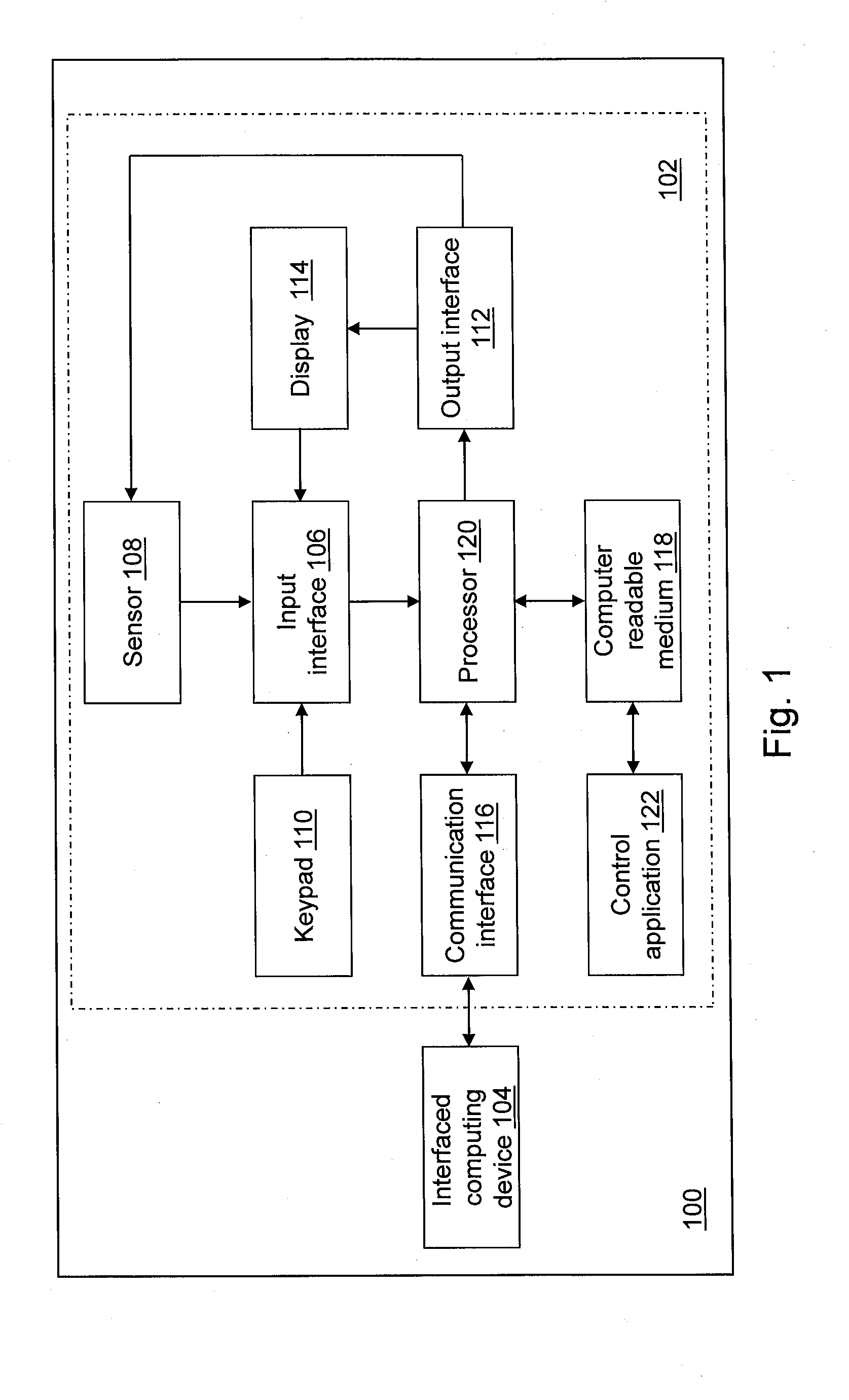
[0023]With reference to FIG. 1, a block diagram of a spectroscopy system 100 is shown in accordance with an illustrative embodiment. In an illustrative embodiment, spectroscopy system 100 may include a spectrometer 102 and an interfaced computing device 104 to which spectrometer 102 may be connected. Spectrometer 102 may not connect to interfaced computing device 104. If connected, spectrometer 102 and interfaced computing device 104 may be connected directly or through a network. The network may be any type of wired and / or wireless public or private network including a cellular network, a local area network, a wide area network such as the Internet, etc. Spectrometer 102 may send and receive information to / from interfaced computing device 104. For example, spectrometer 102 may send results obtained for a sample for storage on interfaced computing device 104. As another example, spectrometer 102 may receive software updates from interfaced computing device 104. Interfaced computing ...


PUM


Abstract

An optical device is provided that includes a converging lens device, a transmitting optical fiber, a sample holder, and a receiving optical fiber. The converging lens device focuses light onto the transmitting optical fiber, which receives the focused light through an entrance face and transmits the light from an exit face, through a sample, and onto the receiving optical fiber. The sample holder holds the sample for analysis. The receiving optical fiber receives the light through an entrance face of the receiving optical fiber after transmission through the sample. The converging lens device is positioned to focus the light onto the entrance face of the transmitting optical fiber such that a half-angle of the angular distribution of the focused light that reaches the entrance face of the transmitting optical fiber is selected to underfill an entrance aperture of the entrance face of the receiving optical fiber in both a spatial dimension and an angular dimension.

Description

BACKGROUND[0001]Optical spectrometers measure the intensity of light at one or more wavelengths to determine certain characteristics of samples, usually liquid samples. The light, usually in the ultraviolet (UV) and / or visible (Vis) wavelength ranges though other wavelength ranges may be used including the near-infrared (NIR) and infrared (IR) wavelengths ranges, is directed through a sample, and the intensity of the output light at the one or more wavelengths is compared to the intensity of the input light at the one or more wavelengths to determine the characteristics of the sample, such as the absorbance, the transmittance, the fluorescence, and / or the reflectance. The measured characteristics provide information about the identity of the components within the sample, their relative concentrations, and possibly other features of the sample. Optical spectrometers are becoming increasingly popular for analysis of small specimens, such as those having a volume of two microliters (μl...

Claims


Application Information

Patent Timeline
IPC IPC(8): G01N21/01
CPCG01J3/0218G01J3/024G01J3/10G01N2021/3181G01N21/3151G01N2021/035G01J3/42
Inventor ASHMEAD, DAMIAN W.DECK, FRANCIS J.
Owner THERMO ELECTRON SCI INSTR
Why Eureka
Try Eureka