Beam scattering laser monitor

a laser monitor and beam scattering technology, applied in the field of laser beam measurements, can solve the problems of more complex and bulky apparatuses, easy interference from extraneous sources of light, etc., and achieve the effect of reducing the level of such particles, avoiding dust contamination problems, and high measurement sensitivity

Active Publication Date: 2013-01-17
OPHIR OPTRONICS SOLUTIONS
View PDF2 Cites 7 Cited by
  • Summary
  • Abstract
  • Description
  • Claims
  • Application Information

AI Technical Summary

Benefits of technology

[0012]Since the level of the Rayleigh scattering is very small, the measurement sensitivity must be high, and is thus susceptible to interference from extraneous sources of light, such as scattering from particles of debris or dust in the measurement field of view, or from illumination coming from the background sources. Signals coming from dust particle scattering are very different from the signals arising from elastic scattering from the air molecules which constitutes the Rayleigh scattering which it is desired to measure. The dust scattered signals are orders of magnitude larger than the Rayleigh scattered signals, and are of a very localized nature both spatially and temporally. The exemplary systems of this disclosure use data processing algorithms that identify such signals scattered from dust and particles, most conveniently by means of pulse height discrimination or pulse width discrimination, and can thus reject data from such regions in the laser beam image. A low pass filter can be effectively used to eliminate sharp intensity pulses due to dust particle scattering. Additionally, in orde

Problems solved by technology

Since the level of the Rayleigh scattering is very small, the measurement sensitivity must be high, and is thus susceptible to interference from extraneous sources of light, such as scattering from particles of debris or dust in the measurement field of view, or from illumination coming from

Method used


Image

  • Beam scattering laser monitor
  • Beam scattering laser monitor
  • Beam scattering laser monitor

Examples


Embodiment Construction

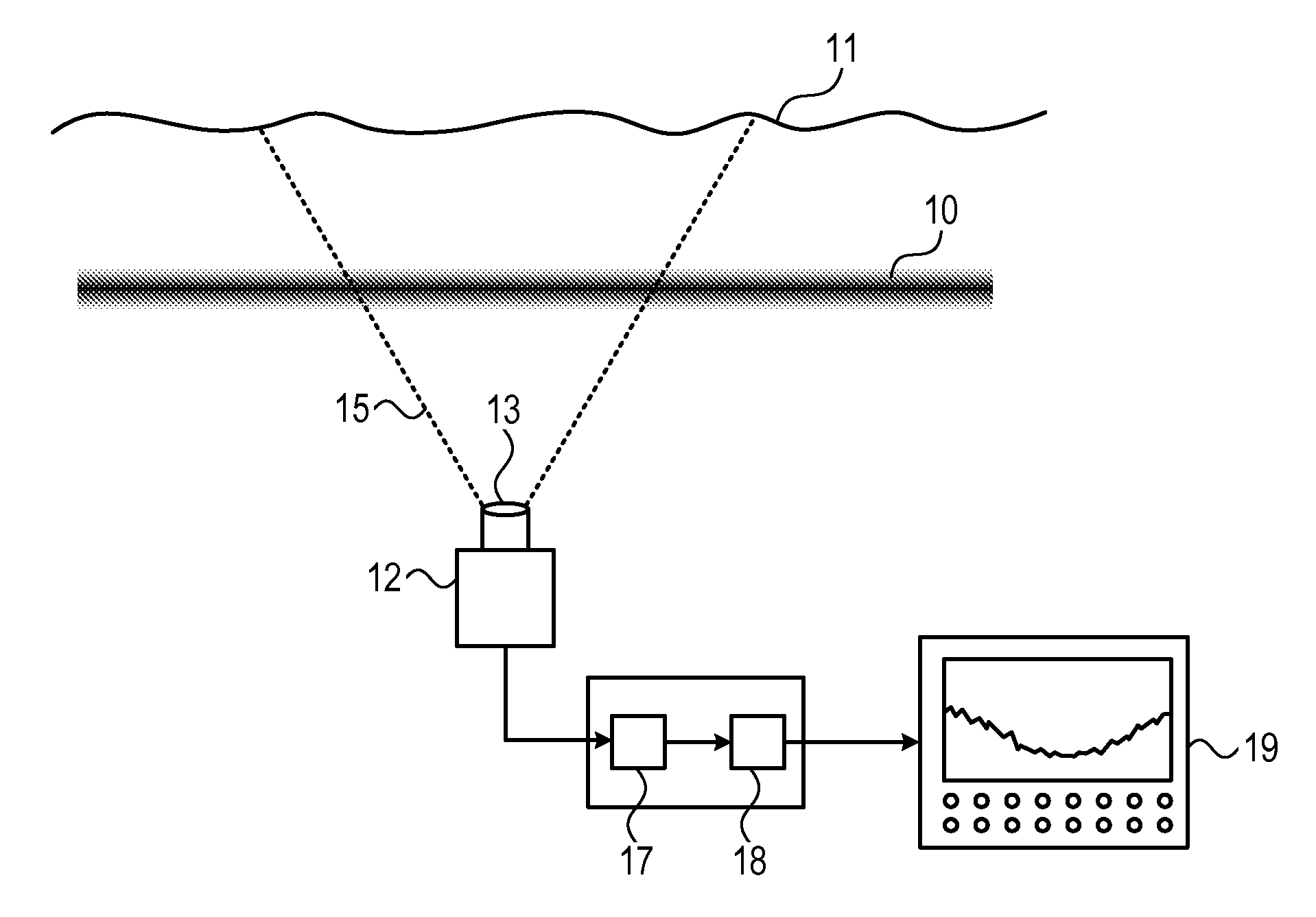
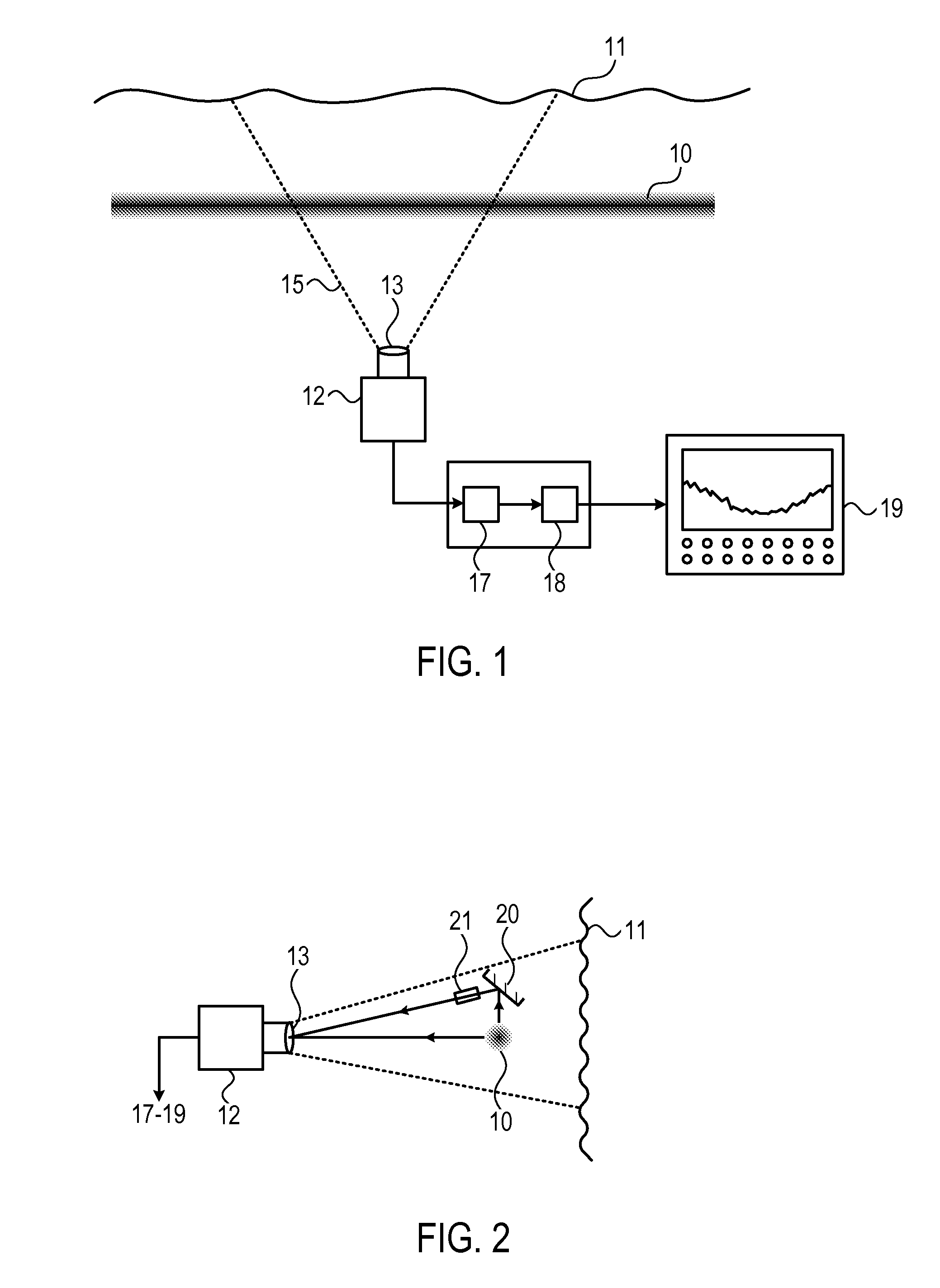
[0046]Reference is now made to FIG. 1, which illustrates schematically an exemplary laser beam characterization system, using Rayleigh scattering measurement, of the type described in this disclosure. The laser beam 10 is directed through a sampling region of interest, which can be the ambient air present in the location where the beam is to be measured. The air molecules in the path of the laser beam Rayleigh scatter the light of the laser beam in all directions. The sampling region is imaged, preferably normal to the direction of the beam path, by an imaging device such as a CCD camera 12 with a lens 13 designed to cover the sampling region of the beam, as indicated by the extremities 15 of the field of view along the beam path direction. Since it is usually desired to image a section of the beam path substantially longer than the beam diameter, the lens can advantageously be of partially cylindrical design, so that each image frame has far more image pixels along the length of th...


PUM


Abstract

New systems for characterizing laser beams, using measurements performed on light which has been Rayleigh scattered from the beam. Different implementations are used for beam profiling, using images of the Rayleigh scattered light, and for laser beam power measurement, using the integrated Rayleigh scattered light. Both of these implementations can be applied to laser beams having high powers, since the measurements do not require insertion of any element into the beam itself, but rather depend on light scattered laterally from the passing beam. The measurements can thus be termed “non contact” measurements, in contrast to prior art methods which require an element inserted into the beam. The systems use Rayleigh scattering from the laser beam passing through ambient air, such that no special scattering chambers or liquids are required for the measurements. Special cancellation algorithms or filters are used to discriminate from light arising from scattering from dust particles.

Description

RELATED APPLICATIONS[0001]This application claims priority from U.S. Provisional Application No. 61 / 340,786, entitled ““Laser beam profiler by air scattering”, filed Mar. 23, 2010, and listing Jeffrey L. Guttman as the first inventor.FIELD OF THE INVENTION[0002]The present invention relates to the field of laser beam measurements using Rayleigh scattering of the air molecules in the path of the laser beam, especially for beam profile measurements and beam power measurements.BACKGROUND OF THE INVENTION[0003]Regarding all laser beams, but especially those for use in material processing applications, the two main beam parameters which a user may need to measure are the total beam power and the spatial profile of the beam. Total beam power is measured by means of a laser power meter, of which many kinds exist in the market. A laser beam profiler measures the spatial irradiance distribution of the laser beam in order to characterize the beam. Beam parameters of interest include diameter,...

Claims


Application Information

Patent Timeline
IPC IPC(8): G01N21/55H04N5/225G06K9/40
CPCG01J1/02G01J1/0214G01J1/4257G01J1/0422G01J1/04
Inventor GUTTMAN, JEFFREY L.FLEISCHER, JOHN M.MINSHALL, MARK E.
Owner OPHIR OPTRONICS SOLUTIONS
Why Eureka
Try Eureka