General-purpose multiple-cutting edge drill

Inactive Publication Date: 2013-01-17
NINGBO HUAREN TOLLS +1
View PDF8 Cites 5 Cited by
  • Summary
  • Abstract
  • Description
  • Claims
  • Application Information

AI Technical Summary

Benefits of technology

[0013]The included angle between the inner cutting edges ranges from about 108° to about 128° and the included angle between the outer cutting edges ranges from about 130° to about 140°. In other words, the included angle between the outer cutting edges is greater than the included angle between the inner cutting edges, which means a length of the drill point of the general-purpose multiple-cutting edge drill is not less than that of a twist drill. So, if viewed from the axial direction, the general-purpose multiple-cutting edge drill provided by the present invention has a structure with a sharp central part and a blunt peripheral part so that both the centering ability of the drill point and the stability of drilling are promoted, which ensures good roundness and axial straight degree of holes when the holes are drilled in solid parts, sheets and pipes.
[0014]The included angle between the outer cutting edges ranging from about 130° to about 140° makes the general-purpose multiple-cutting edge drill applicable to hard materials such as drill steel, cast iron, and stainless steel. And, the included angle between the inner cutting edges ranging from about 108° to about 128° can ensure general-purpose multiple-cutting edge drill provides a sharp drill point and a good centering ability to meet requirements for drilling softer materials such as aluminum, wood, and plastic. Furthermore, because the included angle between the inner cutting edge and the outer cutting edge ranges f

Problems solved by technology

However, in operation, the included angle between two inner cutting edges ranges from about 124° to about 133°, which means there is still a certain increment of the angle included between the two inner cutting edges, so that promotion of the centering ability of the multiple-cutting edge drill is limited to a certain degree.
A length of a dill point of the multiple-cutting edge drill is less than that of a twist drill so that a drilling process performed to thin-wall materials by using the multiple-cutting edge drill is ended before a countersink with an enough size for centering is formed, which induces a poor stabil

Method used


Image

  • General-purpose multiple-cutting edge drill
  • General-purpose multiple-cutting edge drill
  • General-purpose multiple-cutting edge drill

Examples


Embodiment Construction

[0021]Embodiments of the present invention will be described in detail herein in conjunction with the attached drawings.

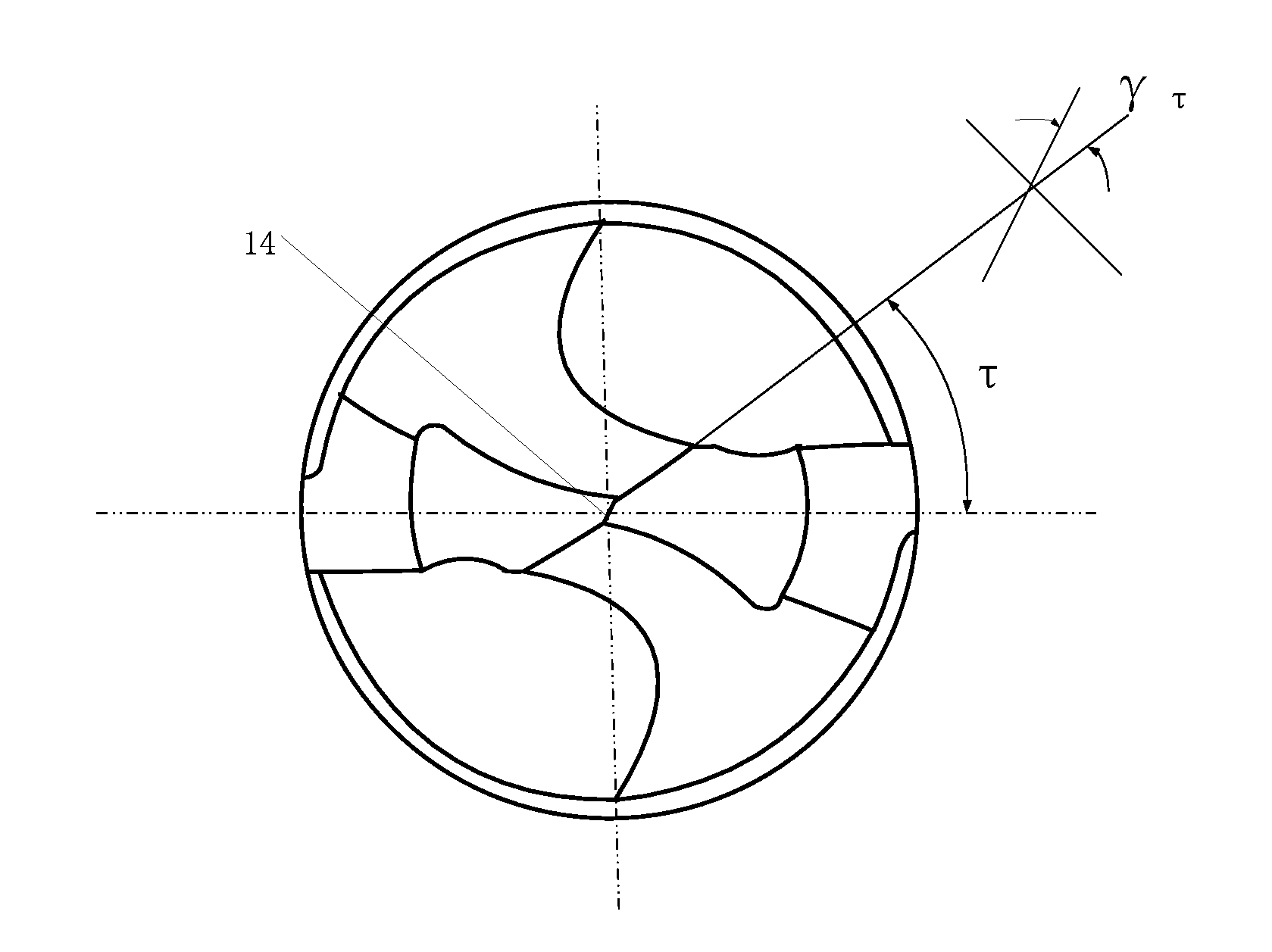
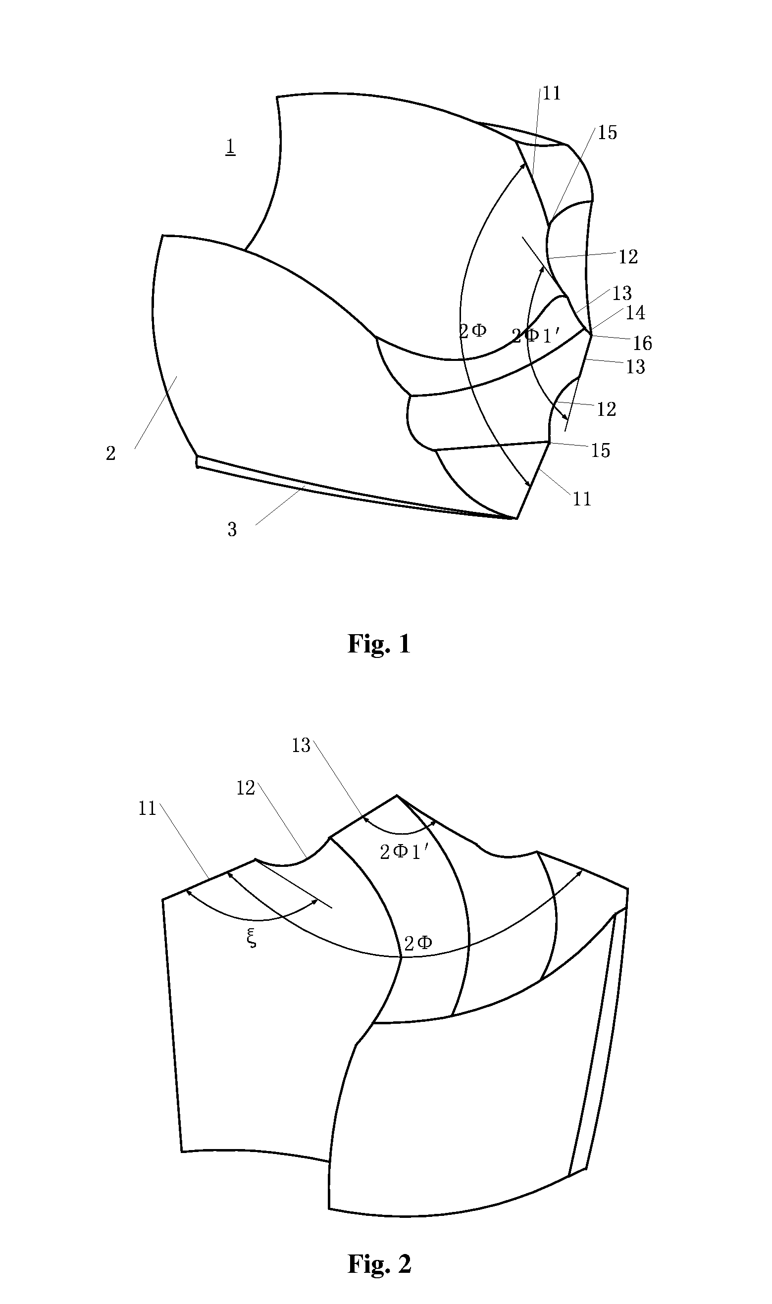
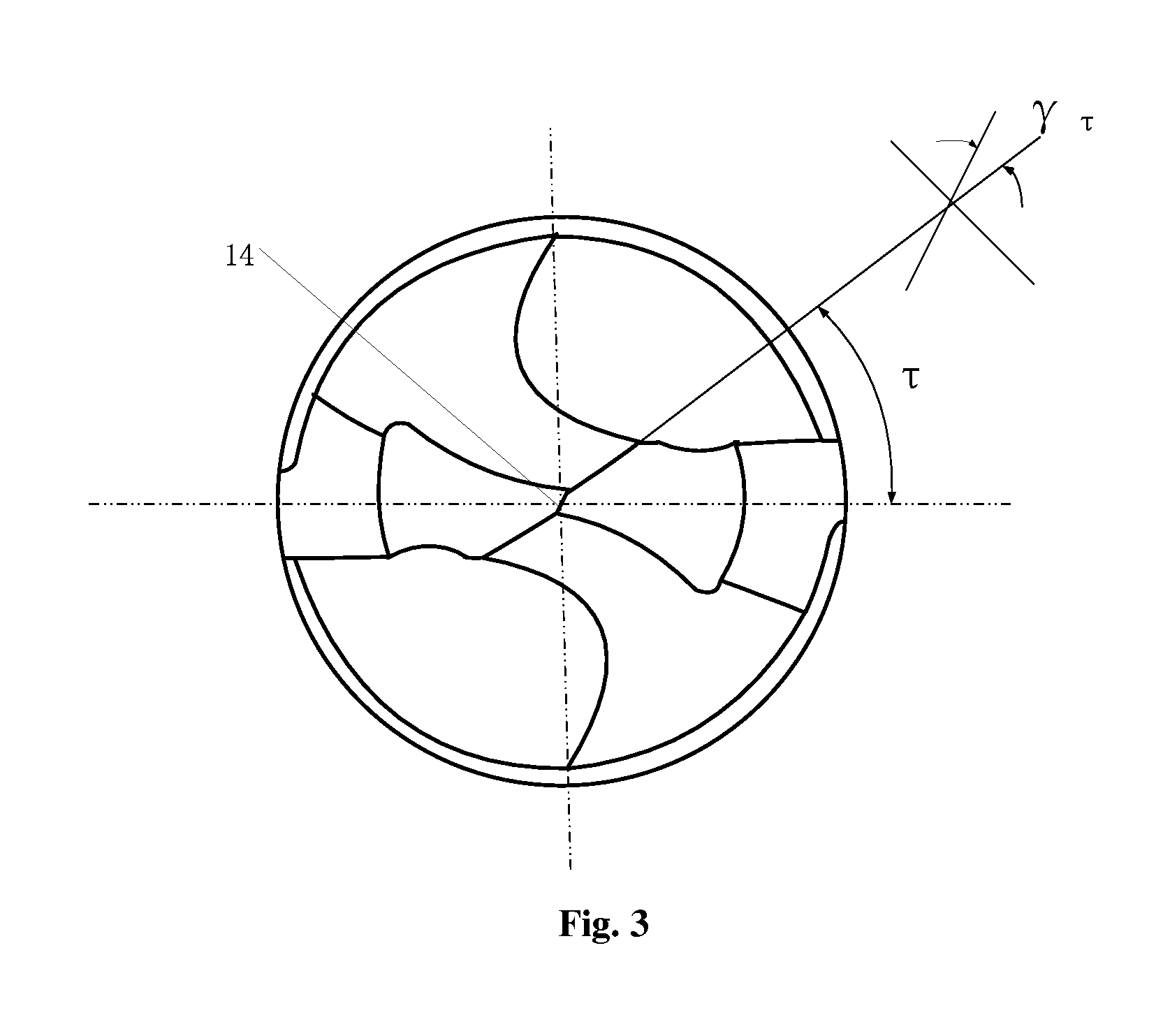
[0022]Referring to FIG. 1 to FIG. 3, a general-purpose multiple-cutting edge drill includes: a drill point 1; a drill body 2 connected with the drill point 1; margins 3 located on an outer wall of the drill body 2; two lips, wherein, if viewed from an axial direction, from out to inside, each of the two lips successively includes an outer cutting edge 11, an arc cutting edge 12 and an inner cutting edge 13; a chisel edge 14 located near a center position of the drill point 1 and between the two inner cutting edges 13; outer peaks 15 formed by intersection of the outer cutting edges 11 and the arc cutting edges 12; and a center peak 16 formed by intersection of two inner flank surfaces and two split surfaces. Therefore, the drill point 1 has a structure with three peaks (two outer peaks 15 and a center peak 16) and seven cutting edges (a chisel edge 14, two inner cu...


PUM

PropertyMeasurementUnit
Angleaaaaaaaaaa
Angleaaaaaaaaaa
Angleaaaaaaaaaa

Abstract

A general-purpose multiple-cutting edge drill includes: a drill point (1); a drill body (2); margins (3) located on an outer wall of the drill body (2); two lips, wherein, if viewed from an axial direction, from out to inside, each of the two lips successively includes an outer cutting edge (11), an arc cutting edge (12) and an inner cutting edge (13); a chisel edge (14); outer peaks (15) formed by intersection of the outer cutting edges (11) and the arc cutting edges (12); a center peak (16) formed by intersection of two inner flank surfaces and two split surfaces. Moreover, an included angle between the inner cutting edges (13) ranges from 108° to 128°, an included angle between the outer cutting edge (11) ranges from 130° to 140°, and an included angle between the inner cutting edge (13) and outer cutting edge (11) ranges from 28° to 40°.

Description

CROSS REFERENCE TO RELATED APPLICATIONS[0001]The present application claims the priority of Chinese Patent Application No. 201120243483.X, entitled “General-Purpose Multiple-Cutting Edge Drill”, and filed on Jul. 11, 2011, the entire disclosure of which is incorporated herein by reference.FIELD OF THE INVENTION[0002]The present invention generally relates to a drilling tool, and more particularly, to a general-purpose multiple-cutting edge drill.BACKGROUND OF THE INVENTION[0003]A multiple-cutting edge drill with a sharp drill point is disclosed in a Chinese patent No. ZL200820165519.5, which has a better centering ability than that of an ordinary multi-facet drill. In addition, by using the multiple-cutting edge drill, a less axial resistance can be achieved.[0004]However, the multiple-cutting edge drill also has the following disadvantages.[0005]In theory, an included angle between two inner cutting edges of the multiple-cutting edge drill can be controlled and does not increase ex...

Claims


Application Information

Patent Timeline
IPC IPC(8): B23B51/02
CPCB23B51/02B23B2251/085Y10T408/909B23B2251/18B23B2251/14
Inventor SUN, JIANING
Owner NINGBO HUAREN TOLLS
Why Eureka
Try Eureka