Rotating electrical machine

a technology of electrical machines and rotating parts, which is applied in the direction of dynamo-electric machines, magnetic circuit rotating parts, and shape/form/construction of magnetic circuits, etc., can solve the problems of inconvenient cooling, inability to know the cooling mechanism, and inability to effectively cool down

Active Publication Date: 2013-01-24
AISIN AW CO LTD
View PDF7 Cites 43 Cited by
  • Summary
  • Abstract
  • Description
  • Claims
  • Application Information

AI Technical Summary

Benefits of technology

[0022]According to this configuration, the coil end portion can be further cooled using the refrigerant after cooling the permanent magnet via the rotor core, whereby the entire rotating electrical machine can be effectively cooled.

Problems solved by technology

However, when the heat generation of the permanent magnet provided in the rotor core proceeds excessively, there is a concern that the permanent magnet may cause irreversible demagnetization.
However, JP 2009-124899 A does not describe a cooling mechanism of the permanent magnet, and, of course, a cooling mechanism is not known yet which is suitable for the rotor core in which the strength tends to decrease by providing the non-magnetic portion.

Method used


Image

  • Rotating electrical machine
  • Rotating electrical machine
  • Rotating electrical machine

Examples


Embodiment Construction

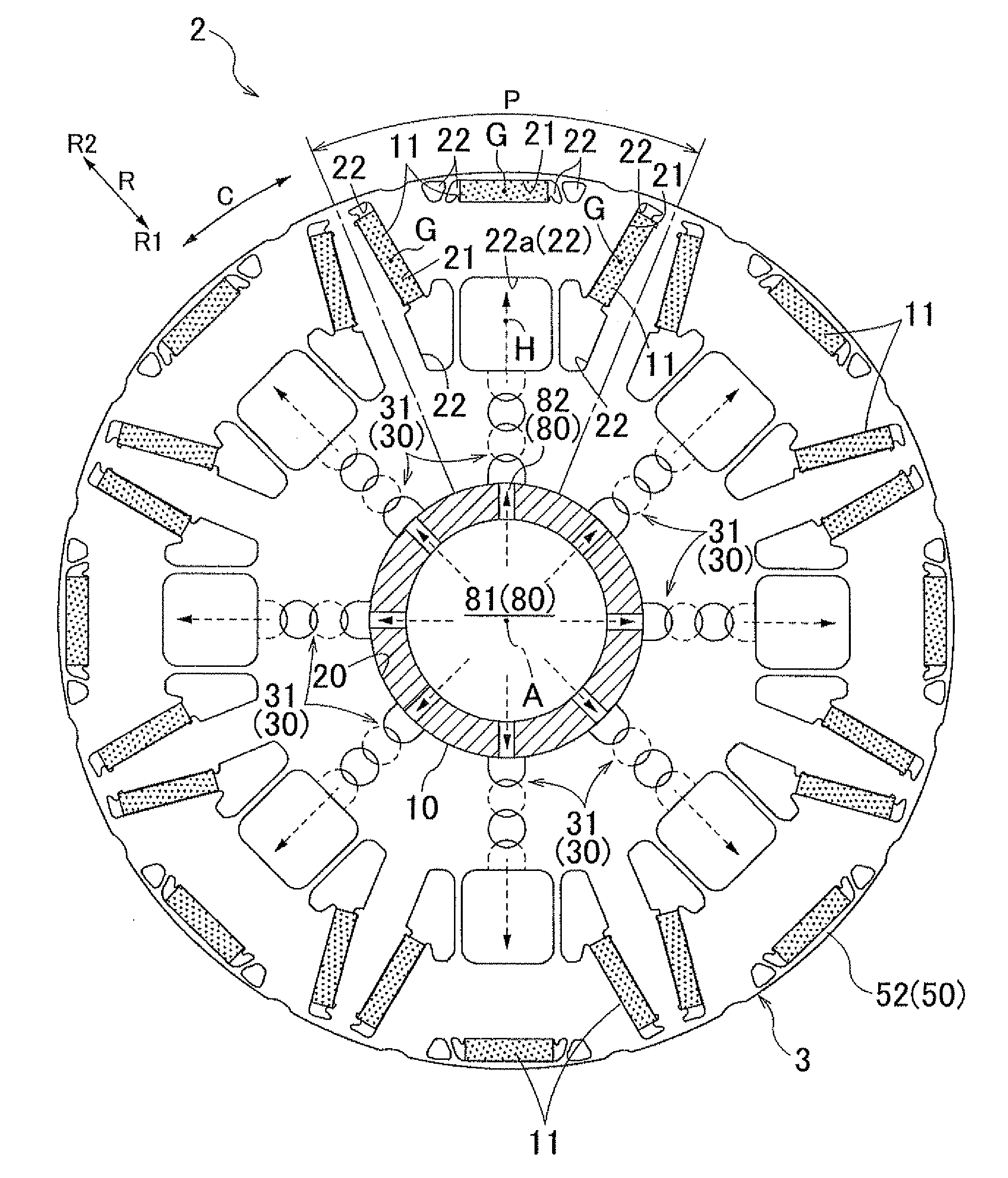
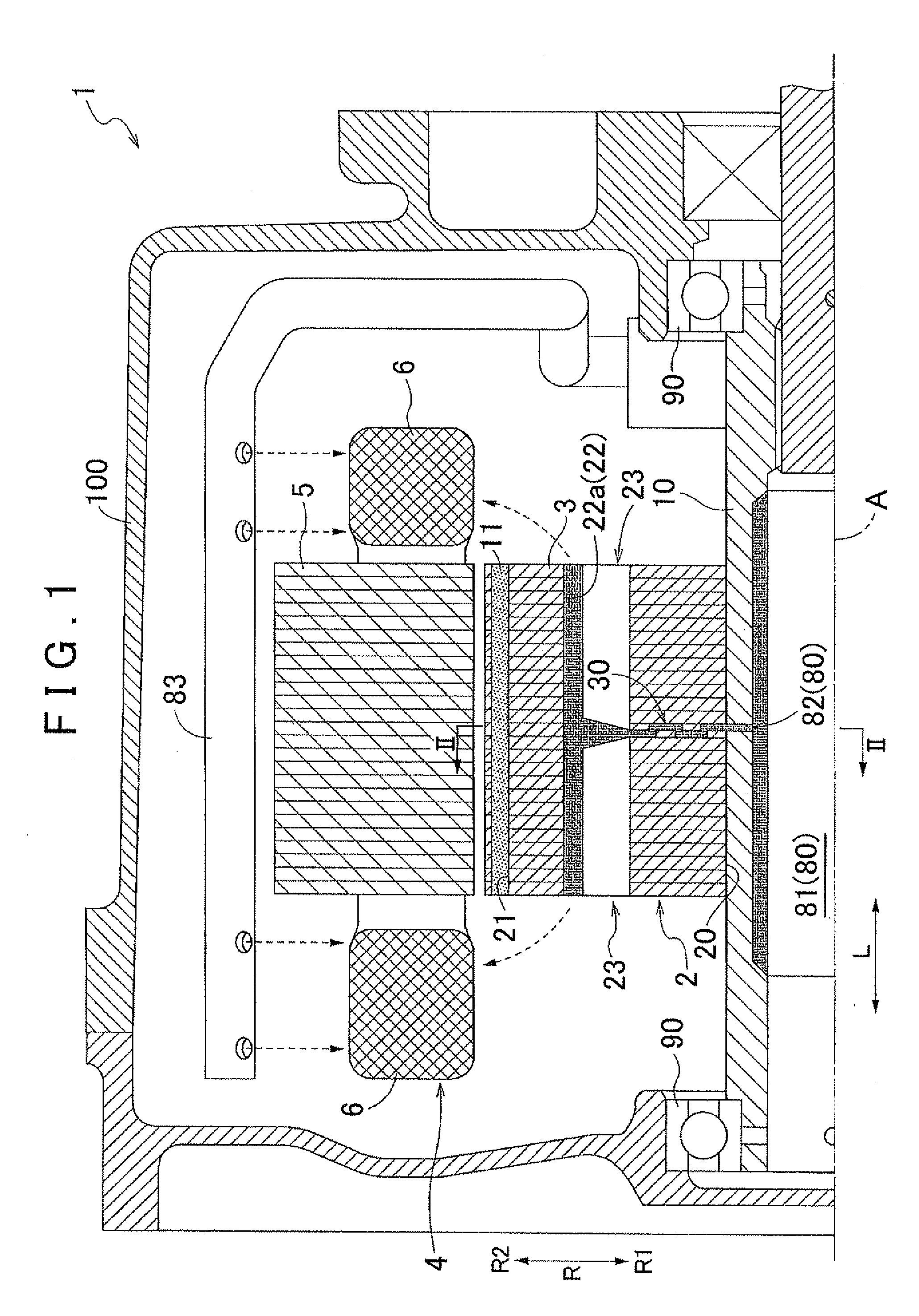
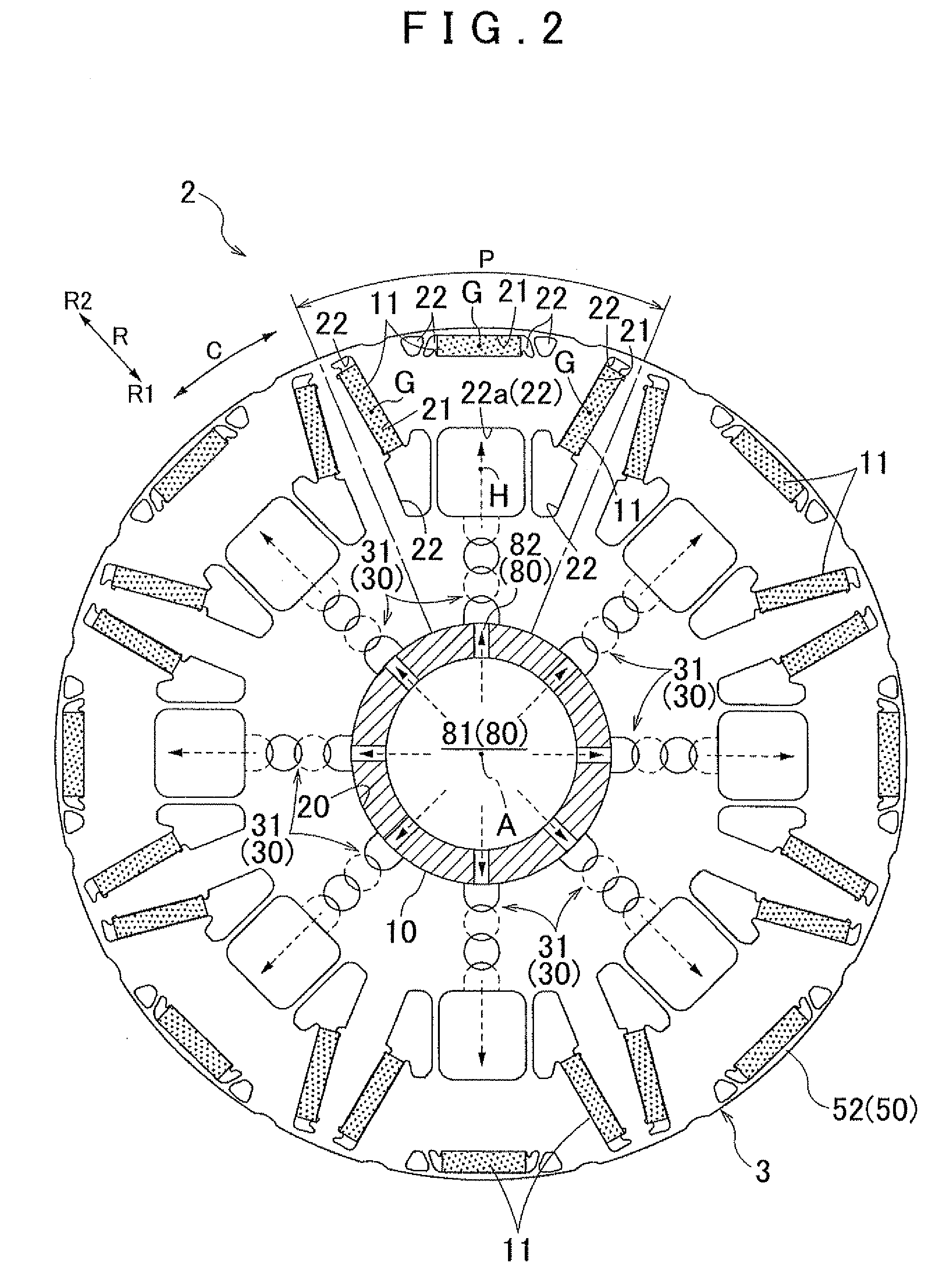
[0033]An embodiment of a rotating electrical machine according to the present invention will be described referring to the drawings. In the description mentioned below, unless otherwise noted, an “axial direction L”, a “diameter direction R”, and a “circumferential direction C” are defined using an axial center A of a rotor core 3 (a rotating electrical machine 1) as a reference (see FIGS. 1 and 2). In addition, a direction of each member indicates a direction in a state where the member is assembled in the rotating electrical machine 1. Furthermore, the descriptions concerning the directions and the positions of the member (for example, “parallel”, “perpendicular” or the like) are used as concepts including the difference corresponding to manufacturing errors. The manufacturing errors are, for example, generated by the deviation in the range of tolerances of a size and an attachment position.

1. Overall Configuration of Rotating Electrical Machine

[0034]An overall configuration of th...


PUM


Abstract

A rotating electrical machine includes a rotor which has a rotor core formed by stacking magnetic plates having an annular plate shape in an axial direction, a permanent magnet is inserted into a magnet insertion hole formed in the rotor core, and a rotor shaft is inserted into a shaft insertion hole surrounded by an inner peripheral surface of the rotor core; and a stator. A radial communication passage is formed by a communication penetration hole group that is formed by sequentially communicating a plurality of the penetration holes from a shaft insertion hole to a magnetic resistance hole in the radial direction. The plurality of the penetration holes are divided into at least two specific magnetic plates and formed such that the radial positions of the penetration holes are different from each other and the penetration holes partially overlap each other when viewed in the axial direction.

Description

INCORPORATION BY REFERENCE[0001]The disclosure of Japanese Patent Application No. 2011-157991 filed on Jul. 19, 2011 including the specification, drawings and abstract is incorporated herein by reference in its entirety.BACKGROUND OF THE INVENTION[0002]The present invention relates to a rotating electrical machine that includes a rotor which has a rotor core formed by stacking a plurality of magnetic plates having an annular plate shape in an axial direction, a permanent magnet inserted into a magnet insertion hole formed in the rotor core and a rotor shaft inserted into a shaft insertion hole surrounded by an inner peripheral surface of the rotor core; and a stator.DESCRIPTION OF THE RELATED ART[0003]As a related art of the rotating electrical machine as mentioned above, for example, there is a technique described in Japanese Patent Application Publication No. 2009-124899 (JP 2009-124899 A) as described below. Hereinafter, in the description of the column of the background art, ref...

Claims


Application Information

Patent Timeline
Patent Type & Authority Applications(United States)
IPC IPC(8): H02K1/32H02K1/27
CPCH02K1/2766H02K1/32H02K9/00H02K1/27H02K9/197H02K9/19
Inventor YAMAMOTO, YOSHIHISAOTAKE, SHINICHITAKEUCHI, TAKAMASASUGIMOTO, MASATOSHIMURAKAMI, SATOSHI
Owner AISIN AW CO LTD
Why Eureka
Try Eureka