Temperature compensation for improved field weakening accuracy

a field-weakening accuracy and temperature compensation technology, applied in the direction of motor/generator/converter stopper, dynamo-electric converter control, dynamo-electric gear control, etc., to achieve the effect of controlling field-weakening accuracy

Inactive Publication Date: 2013-01-24
GM GLOBAL TECH OPERATIONS LLC
View PDF23 Cites 33 Cited by
  • Summary
  • Abstract
  • Description
  • Claims
  • Application Information

AI Technical Summary

Benefits of technology

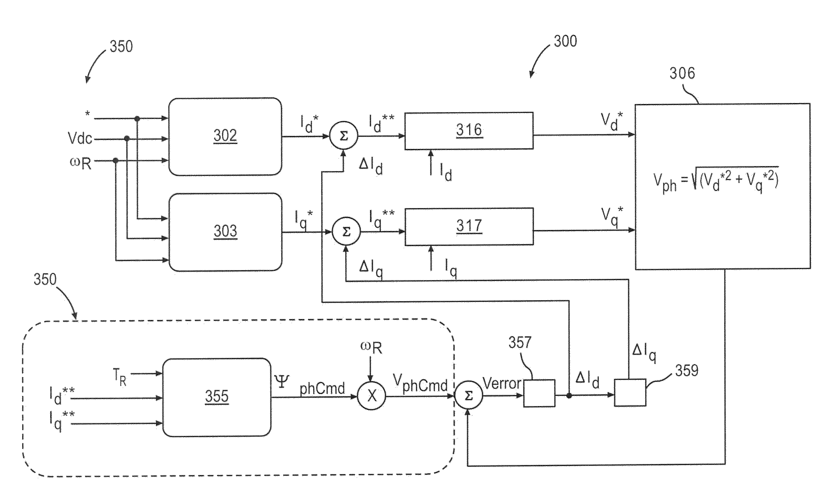
[0010]A method is provided for controlling field-weakening accuracy in an integrated permanent magnet (IPM) electric motor. The method comprises generating a phase voltage feed back signal ΨphCmd based in part on pre-defined optimal current commands (Id** and Iq**) received by the IPM and rotor temperature of IPM machine, generating a phase voltage command VphCmd based in part on rotor speed, current magnitude, stator resistance, and stator a temperature. A phase voltage error Verror is obtained by subtracting phase voltage feedback Vph from phase voltage command VphCmd′. The method further comprises generating a d-axis command current correction value ΔId and a q-axis command current correction value ΔIq from the phase voltage error Verror; and adjusting the pre-defined optimal current commands (ID* and IQ*) by the d-axis and the q-axis command current correction values (ΔId and ΔIq).
[0011]A control loop is provided for field weakening in an electric machine comprising a permanent magnetic rotor. The control loop comprises a first current regulator configured to convert an adjusted current command for the d-axis (Id**) to a synchronous command voltages (Vd*), a second current regulator configured to convert an adjusted current command for the q-axis (Iq**) to a synchronous command voltages (Vq*), and an arithmetic unit configured to generated a phase voltage (Vph) from the synchronous command voltages (Vd* and Vq*). The control loop receives input from a flux linkage correction module, the flux linkage correction module. The flux linkage correction module is configured to receive a rotor temperature (TR) and a rotor speed and is configured to produce a phase voltage command (Vphcmd). The control loop also includes a feed back path configured to subtract the phase voltage (Vph) from the phase voltage command (Vphcmd) and configured to generate both of a d-axis command current correction value ΔId and a q-axis command current correction value ΔIq based on the summation as inputs to the first current regulator and the second current regulator.

Problems solved by technology

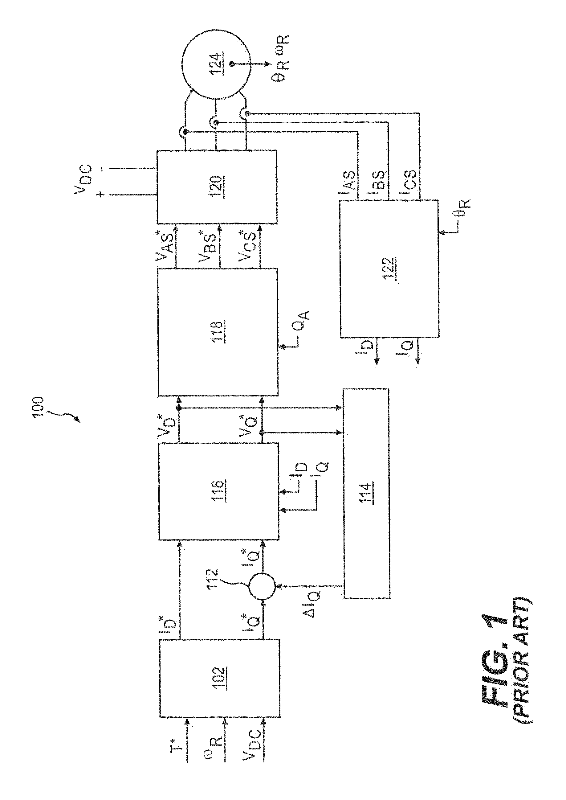
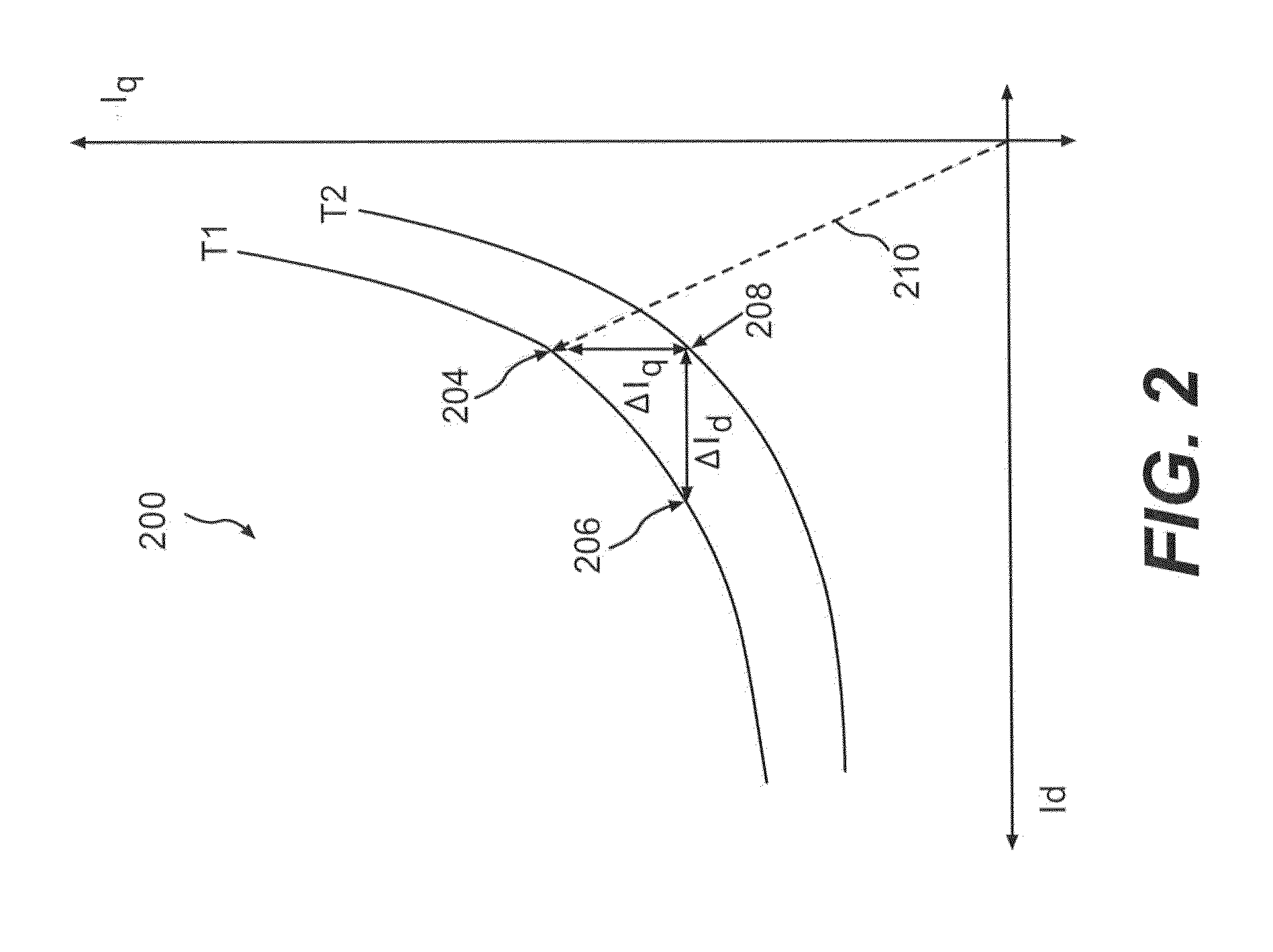
Unfortunately time varying rotor temperature changes cause deviation in the flux produced by the preprogrammed flux weakening currents, thus rendering the pre-programmed flux weakening currents to be sub-optimal for the actual flux being produced.

Method used


Image

  • Temperature compensation for improved field weakening accuracy
  • Temperature compensation for improved field weakening accuracy
  • Temperature compensation for improved field weakening accuracy

Examples


Embodiment Construction

[0021]The following detailed description is merely exemplary in nature and is not intended to limit the invention or the application and uses of the invention. Furthermore, there is no intention to be bound by any expressed or implied theory presented in the preceding technical field, background, brief summary or the following detailed description.

[0022]Embodiments of the invention may be described herein in terms of functional and / or logical block components and various processing steps. It should be appreciated that such block components may be realized by any number of hardware, software, and / or firmware components configured to perform the specified functions. For example, an embodiment of the invention may employ various integrated circuit components, e.g., memory elements, controlled switches, digital signal processing elements, logic elements, look-up tables, or the like, which may carry out a variety of functions under the control of one or more microprocessors or other cont...


PUM


Abstract

Methods and apparatus are provided for rotor and stator temperature compensation for field weakening current. The method comprises generating a phase voltage feed back signal Vph based in part on pre-defined optimal current commands (ID* and IQ*) received by the IPM, generating a phase voltage command (Vphcmd) based in part on a temperature of a magnetic rotor and stator of the IPM, and generating a phase voltage error (Verror) by subtracting the phase voltage feed back signal (Vph) from the phase voltage command (Vphcmd). The method further comprises generating a d-axis command current correction value (ΔId) and a q-axis command current correction value (ΔIq) from the phase voltage error (Verror); and adjusting the pre-defined optimal current commands (ID* and IQ*) by the d-axis and the q-axis command current correction values (ΔId and ΔIq).

Description

TECHNICAL FIELD[0001]The present invention generally relates to electric motors, and more particularly relates to temperature compensation of field weakening current for integrated permanent magnet electric motors.BACKGROUND OF THE INVENTION[0002]An electric machine converts electrical power into mechanical force and motion. Electric machines are found in numerous applications including household appliances such as fans, refrigerators, and washing machines. Electric drives are also increasingly used in electric and hybrid-electric vehicles.[0003]A rotary electric machine generally has an internal rotating magnet, called the rotor, which revolves inside a stationary stator. The interaction between the rotor electromagnetic field with the field created by the stator winding creates the machine torque. The rotor may be a permanent magnet or it may be an electromagnet. However, if the rotor has permanent magnets embedded therein (i.e., the permanent magnets are not in the rotor surface)...

Claims


Application Information

Patent Timeline
Patent Type & Authority Applications(United States)
IPC IPC(8): H02P21/14
CPCH02P21/0089H02P29/0066H02P21/06H02P29/662
Inventor GALLEGOS-LOPEZ, GABRIELDAI, MINWELCHKO, BRIAN A.
Owner GM GLOBAL TECH OPERATIONS LLC
Why Eureka
Try Eureka