Air conditioner, air conditioner manufacturing method, and compressor

a technology of air conditioner and manufacturing method, which is applied in the direction of refrigeration components, magnetic circuits, field or armature current control, etc., can solve the problems of deteriorating long-term operation efficiency, increase the current flowing in the armature winding, and increase the number of rotations of the motor

Active Publication Date: 2011-04-14
DAIKIN IND LTD
View PDF12 Cites 34 Cited by
  • Summary
  • Abstract
  • Description
  • Claims
  • Application Information

AI Technical Summary

Benefits of technology

[0086]According to the first aspect, the residual magnetic flux density of the rare-earth magnet is weakened by the induction heating, thereby enabling a high-speed driving, and a cooling medium is flown near the rare-earth magnet so that the temperature of the cooling medium rises. This can contribute to the heating operation at a time of a high load.
[0087]According to the second aspect, since the magnetic flux weakening control is performed by a current-phase advance at the time of the cooling high-load operation, the number of rotations of the motor can be increased without excessively raising the temperature of the cooling medium.
[0088]According to the third aspect, the voltage applied to the motor is...

Problems solved by technology

Accordingly, if designing is made so as to satisfy requisitions for the heating capability ...

Method used


Image

  • Air conditioner, air conditioner manufacturing method, and compressor
  • Air conditioner, air conditioner manufacturing method, and compressor
  • Air conditioner, air conditioner manufacturing method, and compressor

Examples


first embodiment

Configuration of Axial Gap Type Motor 10A

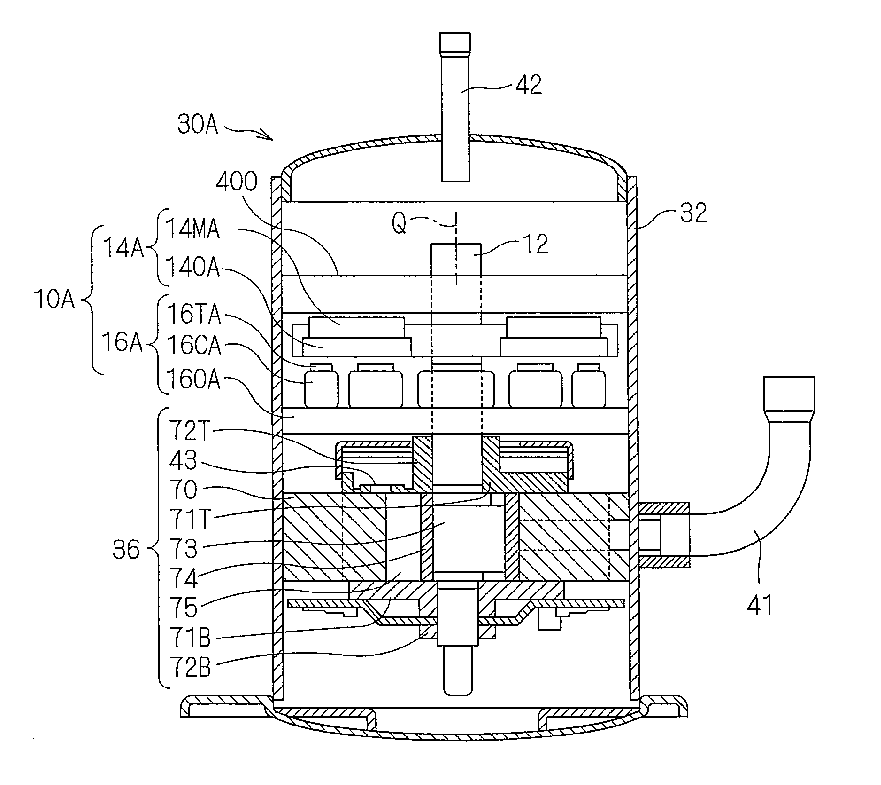
[0218]FIG. 3 is an exploded perspective view of an axial gap type motor 10A, as exploded along a rotation axis Q. The axial gap type motor 10A includes, for example, a rotor 14A as a field element, a stator 16A as an armature, and a magnetic body 400. In an actual configuration, the rotor 14A is interposed between the stator 16A and the magnetic body 400 with slight spaces therebetween.

[0219]The rotor 14A has a rare-earth magnet 14MA, and a rotor core 140A which covers the stator 16A side of the rare-earth magnet 14MA. The rare-earth magnet 14MA is annularly arranged around the rotation axis Q, and a hole 14HA for holding a shaft 12 (see FIG. 4) via a holder frame (not shown) made of a non-magnetic body is formed in the rotor core 140A near the rotation axis Q. Since the rare-earth magnet 14MA and the rotor core 140A are separated corresponding to each magnetic pole, they need be integrated by a non-magnetic body such as a resin. This is serv...

second embodiment

Application Characteristic of Motor Mode

[0294]In this embodiment, a mode in which the compressor 30 has a radial gap type motor 10R mounted therein will be described.

[0295]FIG. 15 is an exploded perspective view of a part of the radial gap type motor 10R, as exploded in a radial direction around the rotation axis Q.

[0296]10R>

[0297]The radial gap type motor 10R includes, for example, a rotor 14R serving as a field element, and a stator 16R serving as an armature. In an actual radial gap type motor, the rotor 14R is opposed to the stator 16R with a slight space interposed therebetween in the radial direction around the rotation axis Q.

[0298]The stator 16R has a yoke 16Y, a teeth 16TR held by the yoke 16Y, and an armature winding 16CR wound on the teeth 16TR as a core. Although two of the teeth 16TR are shown herein, the teeth 16TR are annularly arranged around the rotation axis Q to surround the rotor 14R in the actual motor 10R. The armature winding 16CR is wound in a distributed win...


PUM

PropertyMeasurementUnit
Thicknessaaaaaaaaaa
Forceaaaaaaaaaa
Pressureaaaaaaaaaa

Abstract

At a time of a heating high-load operation, a harmonic current is flown in an armature winding to induction-heat rare-earth magnets, thus reducing a residual magnetic flux density. Thereby, the number of rotations of a radial gap type motor is improved. The rare-earth magnets are provided near a cooling medium passage extending substantially in parallel with a flow line of a cooling medium, so that the cooling medium recovers heat of the heated rare-earth magnets. At a time of a cooling high-load operation, a greater number of rotations are obtained with respect to the same torque command value, by a field weakening control by means of a current-phase advance.

Description

TECHNICAL FIELD[0001]The present invention relates to an air conditioner which performs a heating operation, and to a compressor.BACKGROUND ART[0002]An air conditioner requires a particularly high heating capability, and is designed so as to exert the maximum capacity at a time when a heating operation at a low temperature is started. However, normally, a high heating capability is not so required in a long-term operation. The same applies to cooling. Thus, it is not necessary to particularly increase the ability of a motor in a long-term operation. Especially, a load in a long-term operation state is decreasing year by year because of improved thermal insulation of a building. Accordingly, if designing is made so as to satisfy requisitions for the heating capability at a high-load time, an operating efficiency at a time of the long-term operation is deteriorated. In other words, from the viewpoint of energy saving, it is desired to improve particularly a motor efficiency at a low l...

Claims


Application Information

Patent Timeline
IPC IPC(8): F25B1/00H02K21/12H02P23/00H02K5/18H02K21/24H02K3/34B23P19/04F24F11/46F24F11/49F24F11/62F24F11/86F24F11/88F24F11/89H02K1/27H02K21/14H02P6/06H02P6/08H02P6/15H02P21/00H02P21/02H02P23/02H02P27/04H02P27/08
CPCF25B2600/021H02P21/0089H02K1/2766H02K21/14H02K21/24H02K1/2793H02P27/08H02P21/0042Y10T29/49826F25B49/025H02P29/005Y02B30/741H02P21/26H02P29/62Y02B30/70H02K1/2795
Inventor ASANO, YOSHINARISAKAMOTO, TOMOMIKIFUJI, NOBUYUKIHIGASHI, HIROFUMIARAKI, SHINTAROU
Owner DAIKIN IND LTD
Why Eureka
Try Eureka