Motor controller and electronic power steering apparatus

a technology of electronic power steering apparatus and motor controller, which is applied in the direction of electric generator control, dynamo-electric converter control, dynamo-electric gear control, etc., can solve the problems of large voltage to be applied to the brushless motor, power supply voltage restriction, etc., to reduce the motor torque in the high revolution range, avoid the damage caused by the motor controller, and reduce the effect of the motor torqu

Inactive Publication Date: 2011-02-03
JTEKT CORP
View PDF7 Cites 34 Cited by
  • Summary
  • Abstract
  • Description
  • Claims
  • Application Information

AI Technical Summary

Benefits of technology

[0025]According to the first invention, the d-axis and q-axis current command values are decided not to exceed not only the voltage limit but also the current limit. Therefore, a reduction in the motor torque in the high revolution range can be suppressed by the field weakening control, while avoiding the damage of the motor controller caused due to the event that the excessive current flows through the wirings, the switching elements, etc. in the driving section of the brushless motor, and the like.
[0026]According to the second invention, when the voltage applied to supply the current of the target value to the brushless motor exceeds the limit imposed by the voltage limit value, the voltage that is maximum in the limit range is applied to the brushless motor. Therefore, a reactive power of the brushless motor can be suppressed to the utmost.
[0027]According to the third invention, the q-axis current target value is corrected in the range that does not exceed the voltage limit and the current limit such that a reduction in the motor torque caused due to the d-axis current command value is compensated. Therefore, in addition to the similar advantages to the first or second invention, the stable motor output can be obtained up to the high revolution range eve

Problems solved by technology

Commonly, when the brushless motor is driven at a high revolution and heavy load state, the voltage to be applied to the brushless

Method used


Image

  • Motor controller and electronic power steering apparatus
  • Motor controller and electronic power steering apparatus
  • Motor controller and electronic power steering apparatus

Examples


first embodiment

2. First Embodiment

2.1 Overall Configuration of Motor Control Unit

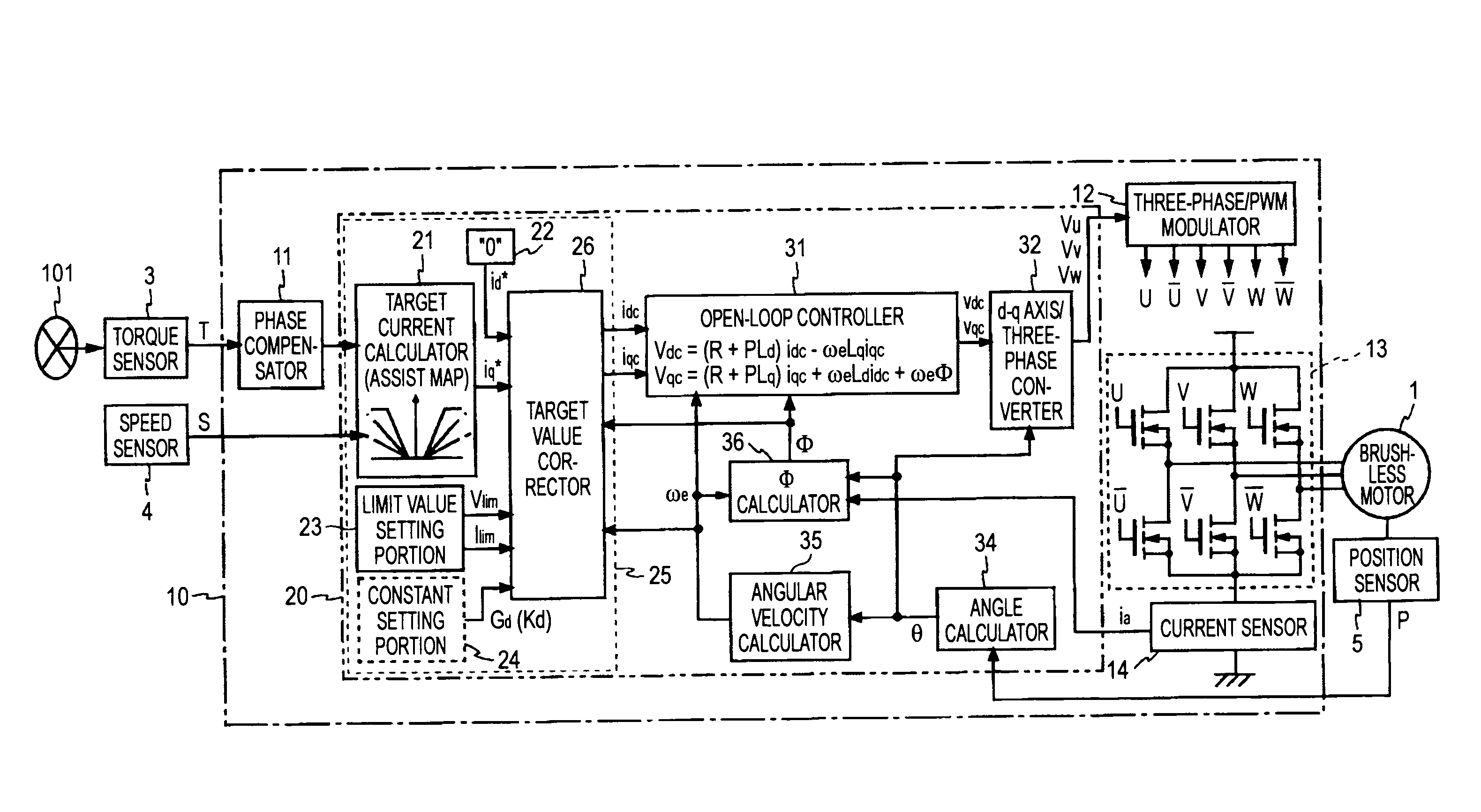
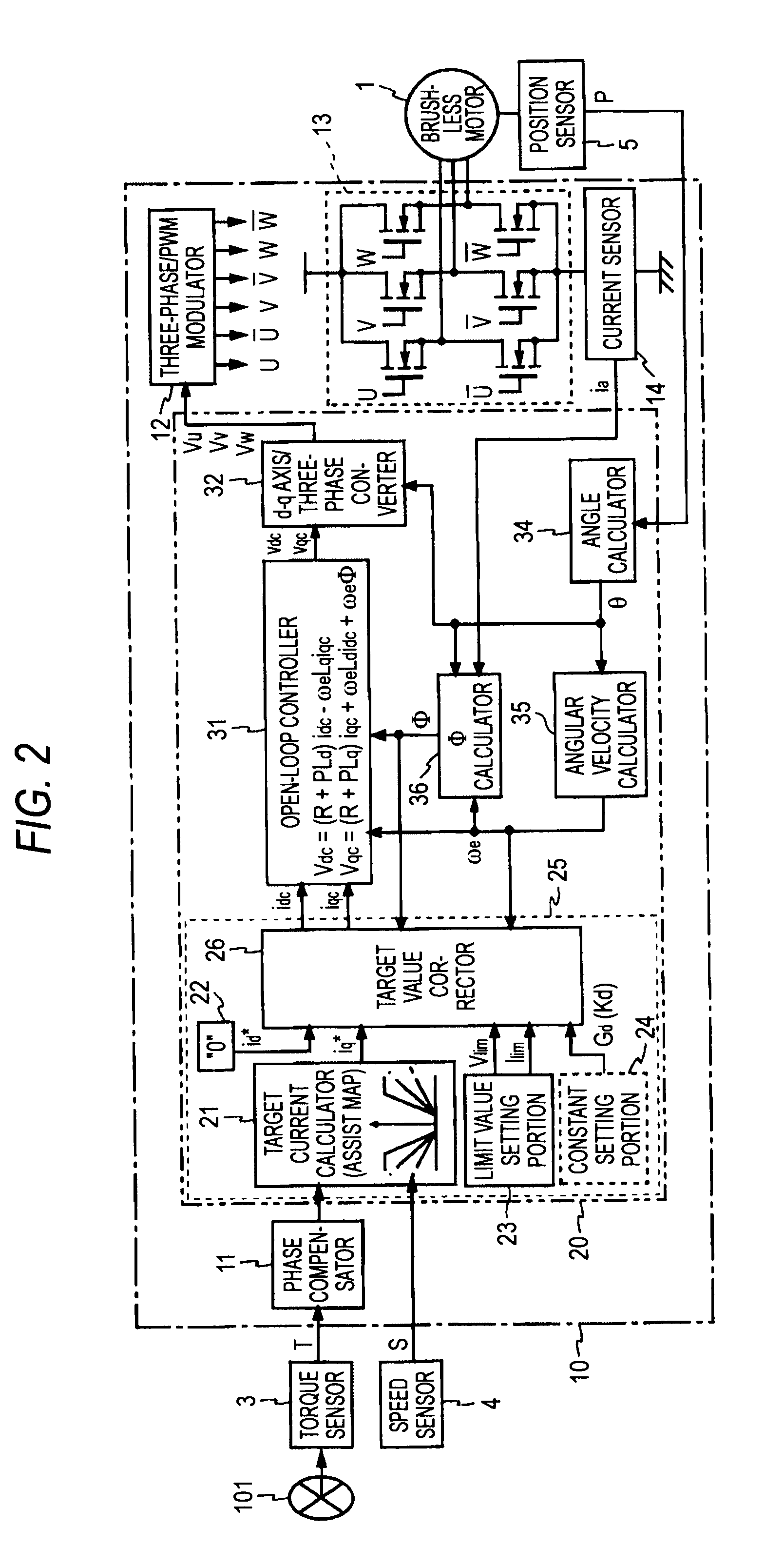
[0050]FIG. 2 is a block diagram showing a configuration of the motor controller according to a first embodiment of the present invention. The motor controller shown in FIG. 2 is constructed by using the ECU 10, and drives the brushless motor 1 with three-phase windings (not shown) in u-phase, v-phase, and w-phase. The ECU 10 is equipped with a phase compensator 11, a microcomputer 20, a three-phase / PWM (Pulse Width Modulation) modulator 12, a motor driving circuit 13, and a current sensor 14.

[0051]The steering torque T output from the torque sensor 3, the vehicle speed S output from the speed sensor 4, and the turning position P output from the position sensor 5 are input into the ECU 10. The phase compensator 11 applies a position compensation to the steering torque T. The microcomputer 20 functions as a controlling section for detecting a voltage command value used to drive the brushless motor 1. Details of function...

second embodiment

3. Second Embodiment

[0118]Next, the motor controller according to a second embodiment of the present invention will be explained hereunder. A basic configuration of the motor controller according to the present embodiment is similar to the first embodiment and is given as shown in FIG. 2, and the same reference symbols are affixed to the same or corresponding portions. In the following, mainly a difference from the first embodiment will be explained hereunder.

[0119]In the present embodiment, the target value correcting process that the microcomputer 20 executes to implement the target value correcting portion 26 is different from the first embodiment. FIG. 10 is a flowchart showing a target value correcting process that the microcomputer 20 executes to implement the target value corrector 26 in the present embodiment. An operation of the target value corrector 26 according to the present configurative example will be explained with reference to FIG. 10 hereunder. Here, the process a...


PUM


Abstract

A command current setting portion has a target value corrector that calculates d-axis and q-axis current command values idc, iqc that are to be supplied to an open-loop controller, based on d-axis and q-axis current target values id*, iq*. When d-axis and q-axis voltage target value vd*, vq* calculated from the d-axis and q-axis current target values id*, iq* by the motor circuit equations exceed a voltage limit, this target value corrector 26 corrects the d-axis and q-axis current target values id*, iq* by the field weakening control such that d-axis and q-axis voltages vd, vq and d-axis and q-axis currents id, iq satisfy √(vd2+vq2)≦Vlim and √(id2+iq2)≦Ilim respectively. The d-axis and q-axis current command values idc, iqc are obtained by this correction.

Description

TECHNICAL FIELD[0001]The present invention relates to a motor controller for driving a brushless motor, and an electronic power steering apparatus equipped with such motor controller.BACKGROUND ART[0002]In the prior art, the electronic power steering apparatus for applying the steering assist force to the steering mechanism of the vehicle by driving the electronic motor in response to the steering torque that the driver applies to the steering wheel (handle) is employed. As the electronic motor of the electronic power steering apparatus, the brush motor is employed widely in the prior art. From the aspects of an improvement in reliability and durability, a reduction in inertia, etc., the brushless motor is also employed nowadays.[0003]Commonly, when the brushless motor is driven at a high revolution and heavy load state, the voltage to be applied to the brushless motor becomes large. But actually the applied voltage to the brushless motor is subjected to restriction of the power sup...

Claims


Application Information

Patent Timeline
IPC IPC(8): H02P21/00B62D5/04H02P27/04H02P27/08
CPCB62D5/046H02P29/022H02P21/06H02P21/0089H02P29/032
Inventor UEDA, TAKESHIKARIATSUMARI, YUJINAGASE, SHIGEKINIGUCHI, NOBORUSUMASU, HIROSHI
Owner JTEKT CORP
Why Eureka
Try Eureka